
A control method and a system for an electric servo system

An electric servo and control method technology, applied in the field of servo control, can solve the problems affecting the dynamic performance and steady-state performance of the system, the inability to effectively compensate unknown nonlinearity, and the complex transmission relationship of the servo system, etc., to reduce online update parameters and calculation costs , fast and precise tracking control, and the effect of reducing the amount of calculation

Active Publication Date: 2019-01-11
EAST CHINA INST OF COMPUTING TECH
View PDF2 Cites 2 Cited by
  • Summary
  • Abstract
  • Description
  • Claims
  • Application Information

AI Technical Summary

Problems solved by technology

However, there is a complex transmission relationship in the servo system, which will cause nonlinear phenomena such as friction nonlinearity and parameter uncertainty, which will affect the dynamic performance and steady-state performance of the system.
At present, the strategy often adopted in practice is PID control. Although this strategy can achieve bounded convergence of tracking error, it cannot effectively compensate unknown nonlinearity, resulting in large tracking error.
In order to achieve nonlinear compensation, intelligent algorithms such as neural network and fuzzy control are generally adopted, but the compensation effect is proportional to the number of neurons, resulting in a large calculation cost and not conducive to practical application

Method used


Image

  • A control method and a system for an electric servo system
  • A control method and a system for an electric servo system
  • A control method and a system for an electric servo system

Examples


Embodiment Construction

[0036] The present invention will be described in detail below in conjunction with specific embodiments. The following examples will help those skilled in the art to further understand the present invention, but do not limit the present invention in any form. It should be noted that those skilled in the art can make several changes and improvements without departing from the concept of the present invention. These all belong to the protection scope of the present invention.

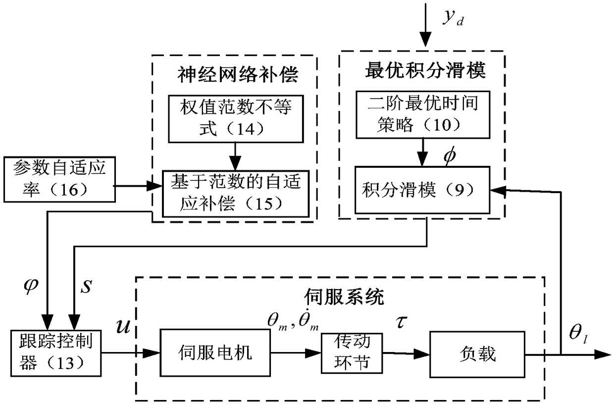
[0037] Schematic diagram of the single-motor drive servo system figure 1 As shown, its main components are servo motor, transmission mechanism and load. The system has complex nonlinearity (such as: friction, transmission relationship, etc.), complex coupling structure (such as: between the motor and the load), and unknown system parameters (such as: friction parameters, torque parameters, etc.), so it has a complex structure and is difficult to control. features. The invention aims at the servo syste...


PUM


Abstract

The invention provides a control method and a system for an electric servo system. The method includes establishing the kinematics model of the electric servo system, substituting the motor load equation in the kinematics model into the load motion equation, obtaining the direct relation between the load and the input control torque through the moment cancellation, transforming the bounded controlvariables into the linear parameterized form by using the bounded time-varying parameters, simplifying the kinematics model into the second-order nonlinear system, obtaining an integral sliding modeby using the optimal time control algorithm of the second-order system, and carrying out the convergence control of the second-order nonlinear system according to the integral sliding mode. The integral sliding mode is obtained by using the optimal time control algorithm of the second-order system, and the convergence of the second-order nonlinear system is controlled according to the integral sliding mode. The invention adopts the optimal integral sliding mode strategy and the norm estimation strategy, thereby reducing the calculation amount and improving the system performance, and facilitating the fast and accurate tracking control of the servo system. It can greatly reduce the on-line update parameters, increase the performance of the system, and provide a new research and developmentideas and application methods for other products and algorithms in the field of servo.

Description

technical field [0001] The invention relates to the field of servo control, in particular to a control method and system for an electric servo system. Background technique [0002] The electric servo system consists of a servo motor, a transmission part, and a load part. The servo motor is the execution part, and the torque is transmitted to the load end through the transmission part to realize the control of the load. Because electric servo has the characteristics of strong driving force and fast response speed, it is widely used in military, industrial, medical equipment and other fields. [0003] With the continuous development of science and technology, the demand for high precision, high stability and fast response of the servo system continues to increase. However, there is a complex transmission relationship in the servo system, which will cause nonlinear phenomena such as friction nonlinearity and parameter uncertainty, which will affect the dynamic performance and ...

Claims


Application Information

Patent Timeline
Patent Type & Authority Applications(China)
IPC IPC(8): H02P29/00H02P23/00
CPCH02P23/0004H02P23/0009H02P23/0018H02P29/00
Inventor 赵威闫朝文
Owner EAST CHINA INST OF COMPUTING TECH
Learn More