A heat sink with a riveting structure and a riveting process thereof

A technology of riveting structure and radiator, which is applied in heat exchange equipment, modification through conduction heat transfer, cooling/ventilation/heating transformation, etc. It can solve the problem of unstable installation, affecting the heat dissipation effect of the radiator, and the radiator is easy to fall off, etc. Problems, to achieve the effect of improving product quality, strong bearing capacity, and improving firmness

Pending Publication Date: 2019-01-11
THERMAL GROUP TECH HUIZHOU
View PDF0 Cites 2 Cited by
  • Summary
  • Abstract
  • Description
  • Claims
  • Application Information

AI Technical Summary

Problems solved by technology

When installing radiator products in the prior art, screw holes or rivet holes are generally processed on the radiator. This processing method is prone to problems such as loose installation and easy falling off of the radiator, which in turn affects the heat dissipation effect of the radiator

Method used


Image

  • A heat sink with a riveting structure and a riveting process thereof
  • A heat sink with a riveting structure and a riveting process thereof
  • A heat sink with a riveting structure and a riveting process thereof

Examples


Embodiment 1

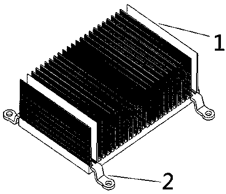
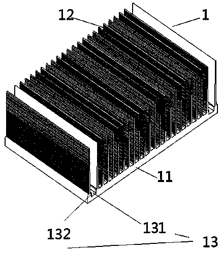
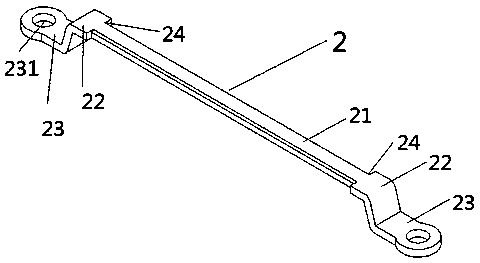
[0033] Figure 1-Figure 3 The schematic diagram of the structure of the radiator with riveted structure, the schematic diagram of the radiator body, and the schematic diagram of the bracket structure of this embodiment are respectively given, combined with reference Figure 1-Figure 3 , a heat sink with a riveting structure, including a heat sink body 1 and a bracket 2; wherein, the heat sink body 1 includes a base 11 and a plurality of cooling fins 12, the cross section of the cooling fins 12 is square, and each cooling fin 12 is parallel to each other, and Vertically arranged on the base 11 at intervals; a groove body 13 is formed between the outermost adjacent heat sinks 12; the groove body 13 includes a mounting groove 131 and a pre-cut groove 132, the mounting groove 131 is located on the base 11, and the pre-cut groove 132 is located on the Both sides of the installation groove 131, and the position of the pre-cut groove 132 is higher than the installation groove 131; th...

Embodiment 2

[0039] Figure 4-6 Partial cross-sectional views of the heat sink with riveted structure in this embodiment at the beginning of riveting are given respectively Figure 1 , Partial cross-section in the process of deformation riveting Figure II , Partial cross-section after deformation riveting Figure three , combined with reference Figure 4-6 , the present embodiment provides a riveting process for a heat sink with a riveting structure, comprising the following steps,

[0040] S1. Process an installation groove 131 and a pre-cut groove 132 in the tank body 13, the installation groove 131 is located on the base 11, the pre-cut groove 132 is located on both sides of the installation groove 131, and the position of the pre-cut groove 132 is higher than the installation groove 131;

[0041] S2. Process the punching head 31 corresponding to the pre-cut groove 132 at the lower end of the riveting punch 3;

[0042] S3. Put the radiator body 1 on the stamping equipment, and put ...


PUM

PropertyMeasurementUnit
mechanical propertiesaaaaaaaaaa

Abstract

The invention discloses a heat sink with a riveting structure, comprising a heat sink body and a bracket, wherein the heat sink body comprises a base and a plurality of heat sink fins, wherein the heat sink fins are parallel to each other and are arranged on the base at intervals; Forming a groove body between the outermost adjacent heat dissipation fins. The bracket comprises a fixed position, two bending positions and two mounting positions, wherein the fixed position is in the shape of a strip, the bending positions are respectively located at both ends of the fixed position, and the mounting positions are respectively located at the outside of the bending position. The fixing position is riveted in the groove body. The invention also discloses a riveting process of the radiator, whichis simple in riveting process, compact in structure and high in heat dissipation effect.

Description

technical field [0001] The invention relates to the technical field of heat sinks, and more specifically, to a heat sink with a riveted structure and a riveting process thereof. Background technique [0002] A radiator is a general term for a series of devices used to conduct and release heat. When installing radiator products in the prior art, screw holes or rivet holes are generally processed on the radiator. This processing method is prone to problems such as loose installation and easy falling off of the radiator, which in turn affects the heat dissipation effect of the radiator. Therefore, it is necessary to improve the installation structure of the radiator. Contents of the invention [0003] The main purpose of the present invention is to overcome the above disadvantages and provide a heat sink with a riveted structure and a riveted process thereof, which has a compact structure, high heat dissipation effect, and simple riveted process. [0004] Technical scheme o...

Claims


Application Information

Patent Timeline
Patent Type & Authority Applications(China)
IPC IPC(8): H05K7/20B21D39/00B21D53/02
CPCH05K7/2039B21D39/00B21D53/02
Inventor 姜文新邓中应谭弘平
Owner THERMAL GROUP TECH HUIZHOU
Why Eureka
Try Eureka