
Metal magnetic lining plate formed by reinforcing protective layer

A technology to strengthen the protective layer and metal magnetism, which is applied in the direction of grain processing, etc., can solve the problems of weakening the wear resistance of the magnetic lining, weakening the firmness of the protective layer⑾, and shortening the service life, so as to prolong the service life and reduce the leakage of ore slurry , The effect of saving power consumption

Inactive Publication Date: 2019-01-11
BEIJING HIGH MILL TECH CO LTD +2
View PDF9 Cites 0 Cited by
  • Summary
  • Abstract
  • Description
  • Claims
  • Application Information

AI Technical Summary

Problems solved by technology

[0006] In order to solve the problem that the polar ribs (4) of the existing metal magnetic lining are located at the Y−Y section of the magnetic lining working face with the highest magnetic field intensity, so that they stay in the shallow groove (6) surrounded by the polar ribs (4) and the transverse ribs (5). The protective layer ⑾ is interrupted at the Y−Y section with the highest magnetic field intensity, which weakens the firmness of the protective layer ⑾, thereby weakening the wear resistance of the magnetic lining and shortening its service life. The present invention proposes a Metal magnetic liner formed by reinforced protective layer

Method used


Image

  • Metal magnetic lining plate formed by reinforcing protective layer
  • Metal magnetic lining plate formed by reinforcing protective layer
  • Metal magnetic lining plate formed by reinforcing protective layer

Examples


Embodiment 1

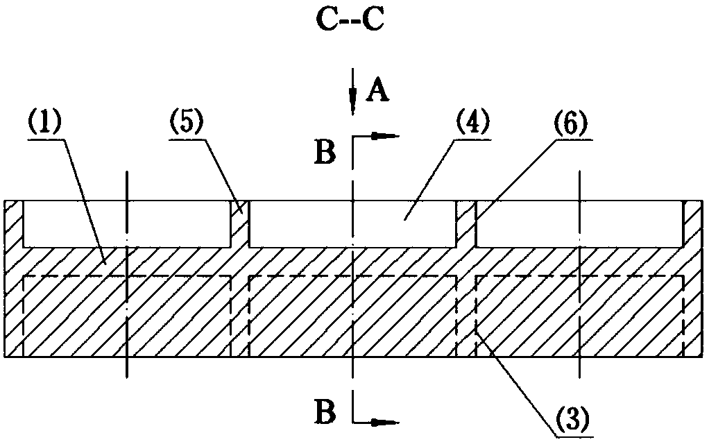
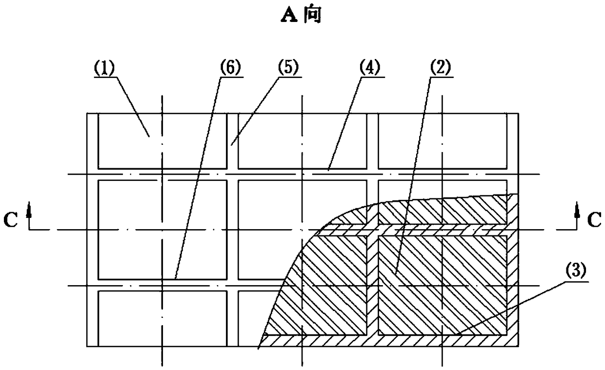
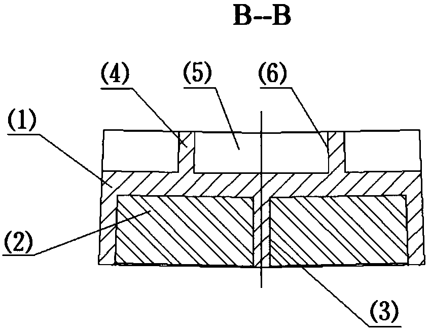
[0047] The second overflow type ball mill, the specification is Φ3.6m×6.0m. The material is magnetite, and the diameter of the steel ball is ≤60mm. A metal magnetic liner formed by a reinforced protective layer of the present invention adopting the basic structure, such as Figure 1 ~ Figure 3 shown.

[0048] The magnetic liner is composed of the shell ⑴, the magnetic block group ⑵ and the adhesive. The shell (1) is cast according to the chemical composition of non-magnetic steel. One side is the installation surface, which is composed of 6 cube-shaped lattices (3) arranged in 2 rows and 3 columns; the other side is the working surface, which consists of 2 pole ribs (4) and 4 transverse ribs. Plates (5) enclose shallow grooves (6), polar ribs (4) are located in the symmetrical center plane of each row of grids (3), transverse ribs (5) are perpendicular to polar ribs (4), and are aligned with the side walls of grids (3). Each magnetic block group ⑵ is composed of 2 ferrite m...

Embodiment 2

[0052] The second stage of overflow ball mill, specification Φ5.0m×6.5m. The material is magnetite, and the diameter of the steel ball is ≤60mm. A metal magnetic liner formed by a reinforced protective layer of the present invention that adopts an inlaid hemispherical magnetizer (7), such as Figure 4 ~ Figure 6 shown.

[0053] The magnetic liner is composed of the shell ⑴, the magnetic block group ⑵ and the adhesive. First cast the magnetizer (⑺) according to the chemical composition of the wear-resistant magnetic steel, and then cast the shell (1) according to the chemical composition of the non-magnetic steel, and cast the magnetizer (7) on it during the process of casting the shell (1). Heat treatment is carried out using a process suitable for both the shell (1) and the magnetizer (7). One side of the housing (1) is the mounting surface, which consists of 6 cube-shaped grids (3) arranged in 2 rows and 3 columns; the other side is the working surface, the magnetizer (7)...


PUM

PropertyMeasurementUnit
diameteraaaaaaaaaa

Abstract

A metal magnetic lining plate formed by reinforcing a protective layer for protecting the inner surface of a mill cylinder and the ferromagnetic metal surface of the material in contact with the material during material transportation to reduce the wear of the surface. The lining plate is composed of a casing (1), a magnetic block group (2) and an adhesive; wherein the casing (1) is made of a non-magnetic metal material, one side is a mounting surface, and is composed of a plurality of cubic lattices (3), and all lattices (3) are aligned horizontally and vertically. The other side is a workingsurface, which is surrounded by the pole rib plates (4) and the transverse rib plates (5) into shallow grooves (6). A magnetic block group (2) is placed in the lattice (3). The polarity direction ofthe magnetic block groups (2) loaded into the lattices (3) is such that the polarities of the same row of magnetic block groups (2) are the same, and the polarities of the adjacent two rows of magnetic block groups (2) are opposite. The pole rib plates (4) on the working surface of the outer casing (1) are located in a symmetrical center plane of a row of lattices (3) in which the magnetic block groups (2) of the same polarity are mounted. The above arrangement of the pole rib plates (4) allows the protective layer (11) residing in the shallow grooves (6) surrounded by the pole rib plates (4)and the transverse rib plates (5) to remain continuous in the region of the highest magnetic field strength, whereby the protective layer (11) is more strongly sucked in the shallow grooves (6), the magnetic liner working surface is better protected and the magnetic liner life is extended.

Description

technical field [0001] The invention relates to the protection of the mill barrel used in grinding mills for metal minerals, industrial minerals, chemical minerals, energy minerals and building materials, as well as the protection of ferromagnetic metal surfaces of equipment in contact with materials during material transportation to reduce wear on these surfaces A metal magnetic liner formed by a reinforced protective layer. Background technique [0002] The structure of the existing metal magnetic liner ⑿ is as follows Figure 13 ~ Figure 15 or Figure 16 ~ Figure 18 shown. Figure 13 ~ Figure 15 The metal magnetic liner shown is composed of the shell ⑻, the magnetic block group ⑵ and the adhesive. The shell ⑻ is made of non-magnetic metal material. One side is the installation surface, which is composed of multiple cube-shaped grids ⑶, and each grid ⑶ is arranged in an array aligned horizontally and vertically; the other side is the working surface, which is composed of ...

Claims


Application Information

Patent Timeline
Patent Type & Authority Applications(China)
IPC IPC(8): B02C17/22B02C23/00
CPCB02C17/22B02C23/00B02C2210/02
Inventor 魏明安武文建吴建明
Owner BEIJING HIGH MILL TECH CO LTD
Learn More