Spherical orthodontic arch wire bending robot and use method thereof

An orthodontic archwire and robot technology, applied in the field of spherical orthodontic archwire bending robots, can solve problems such as slipping and warping, hindering the bending process, and easy interference, achieving rapid response, flexible adjustment, and satisfying institutional rigidity Effect

Active Publication Date: 2019-01-15
HARBIN UNIV OF SCI & TECH
View PDF9 Cites 1 Cited by
  • Summary
  • Abstract
  • Description
  • Claims
  • Application Information

AI Technical Summary

Problems solved by technology

[0003] For example, the orthodontic archwire bending robots described in the invention patent authorization announcement number of CN 103892929 B and the utility model patent authorization announcement number of CN203898469 U all adopt the Cartesian coordinate movement mode, mainly moving in three directions of the Cartesian coordinates. Based on this, some degrees of freedom are added to complete the corresponding bending operation, and then the design of the motion scheme of the entire orthodontic archwire bending robot is completed. However, in the actual bending process, due to the certain spatial structure of the formed part, the feeding The wire will occupy a large space during the rotation process, which makes the orthodontic archwire bending robot prone to interference and hinders the bending process. The mold cannot clamp the orthodontic archwire. Therefore, during the bending process of the orthodontic archwire bending robot, there is a bending gap between the chuck of the bending mold and the orthodontic archwire. The bending gap will cause the orthodontic archwire Sliding and warping occurs at the deformed part, which further reduces the quality of the orthodontic archwire bending robot, making it impossible for the orthodontic archwire bending robot to bend the ideal orthodontic archwire
Due to the structural limitations of the Cartesian coordinate orthodontic archwire bending robot, it is easy to interfere and slip and warp during the bending process, so that the Cartesian coordinate orthodontic archwire bending robot can only bend the first sequence Curves and individual second-sequence tunes, which cannot meet the requirements of doctors and patients for all second-sequence tunes
[0004] Similarly, although the Cartesian coordinate type orthodontic archwire bending robot whose utility model patent authorization announcement number is CN 204562423 U can bend the T-shaped bend by changing the radius of curvature of the orthodontic archwire bending angle, the Cartesian coordinate The orthodontic archwire bending robot combined with the traditional bending method still cannot avoid the limitations of the Cartesian coordinate structure, so that the orthodontic archwire bending robot cannot surpass the manual bending, and cannot break through the orthodontic archwire bending robot. Key Technical Difficulties
[0005] A similar patent also has a bending device for an orthodontic archwire bending robot with the authorized announcement number CN 205324558 U. This patent realizes the clamping and feeding of the orthodontic archwire through the positive and negative rotation of the motor , but the bending device has a complex structure, and can only realize the clamping and loosening of the orthodontic archwire, and cannot bend complex sequence curves. Compared with the above two rectangular coordinate-type orthodontic archwire bending robots, this patent Limited functions, small scope of application
[0006] A comprehensive analysis of the existing orthodontic arch wire bending robots can only achieve the bending of the first sequence of bows and a few simple second sequence of bending, while dental wire bending technicians can flexibly bend such as Omega, Arch wires with special shapes such as T-shaped curves, teardrop curves, and box-shaped curves are used for clinical treatment. In addition, dental wire bending technicians can bend personalized orthodontic arch wires according to the actual conditions of different patients. Orthodontic archwires need to contain one or more special functional curves of the second and third sequences, with different structural complexity, including various types and numbers of the second and third sequences of curves, and in bending personalized orthodontics When archwire is used, the bending space is narrow, which makes the orthodontic archwire robot prone to interference problems during the bending process. Therefore, the development of orthodontic archwire robot technology is restricted.
In addition, in the actual arch wire bending process, the bending mold used by the rectangular coordinate orthodontic arch wire bending robot cannot clamp the orthodontic arch wire so that a bending gap is generated during the bending process, resulting in slippage and warping. This kind of bending method also causes the bent orthodontic archwire to be in the cantilever beam state, which affects the bending accuracy of the orthodontic archwire bending robot. By comparing the above-mentioned existing Cartesian coordinate formula Orthodontic archwire robot, designed a spherical orthodontic archwire bending robot

Method used


Image

  • Spherical orthodontic arch wire bending robot and use method thereof
  • Spherical orthodontic arch wire bending robot and use method thereof
  • Spherical orthodontic arch wire bending robot and use method thereof

Examples


Embodiment 1

[0031] Embodiment 1: as figure 1 , figure 2 , image 3 , Figure 4 , Figure 5 , Image 6 , Figure 7 , Figure 8 , Figure 9 As shown, this embodiment adopts the following technical solutions:

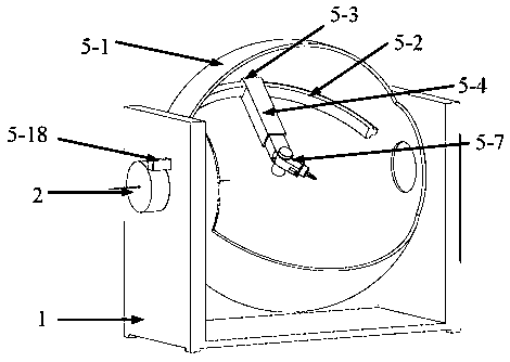
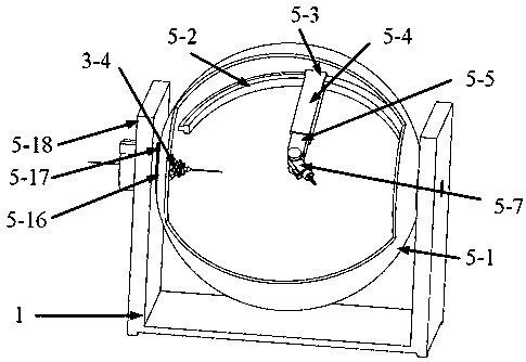
[0032] A spherical orthodontic archwire bending robot and its use method, it includes a base support 1, a wire feeding mechanism 2, an angle adjustment mechanism 3, an archwire clamping mechanism 4 and a wire bending mechanical arm 5, the wire feeding mechanism 2 Connected to the outside of the left side of the base bracket 1 by bolts, the angle adjustment mechanism 3 is fixed to the inside of the left side of the base bracket 1 by bolts, the archwire clamping mechanism 4 is fixedly connected to the top of the angle adjustment mechanism 3, and the wire bending mechanical arm 5 is located in the middle part of the left and right sides of the base support 1, and is connected to the base support 1 through bearings.

[0033] Further, the wire feeding mechanism 2 includes a wire ...

Embodiment 2

[0037] Embodiment 2: The initial power-on position of the spherical orthodontic archwire bending robot;

[0038] According to the device described in Embodiment 1, when the spherical orthodontic archwire bending robot is in the initial power-on state, the angle adjustment platform I3-1, the angle adjustment platform II3-2, and the angle adjustment platform III3-3 are parallel to each other and parallel to each other. Perpendicular to the horizontal line, the angle platform II linear motor 3-4 and the angle platform III linear motor 3-5 are in contraction state; the clamping head shell 4-1 and the separate chuck 4-2 at the end of the angle adjustment platform III3-3 They are in contact with each other but not pressed tightly, the inner ring of the electromagnet 4-3 is in contact with the separate chuck 4-2 but not pressed tightly, the outer ring of the electromagnet 4-5 is in a power-off state, and the outer shell of the clamping head 4-1 is separated from the The tapered surfa...

Embodiment 3

[0039] Embodiment 3: The specific implementation of the spherical orthodontic archwire bending robot to complete the wire bending task;

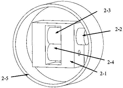
[0040] According to the device described in Embodiment 1, when the wire bender needs to bend the orthodontic archwire, the archwire is sent from the wire feeding housing 2-5 to the active pressure roller 2-3 and the passive pressure roller 2- 4, the wire feeding motor 2-2 drives the active pressure roller 2-3 to drive the passive pressure roller 2-4, so that the arch wire is sent into the flexible hose 4-6 and reaches the clamping head shell 4-1; After the electromagnet outer ring 4-4 ​​is powered on, the electromagnet inner ring 4-3 moves toward the clamping head shell 4-1, thereby pushing the split chuck 4-2 to the clamping head shell 4-1, and because The clamping head shell 4-1 and the tapered surface of the split chuck 4-2 are in contact with each other and press fit, so that the split chuck 4-2 is clamped, wherein the flexible hose 4-6 ...


PUM


Abstract

The invention discloses a spherical orthodontic arch wire bending robot and a use method thereof and belongs to the field of orthodontic arch wire bending. The robot comprises a base bracket, a wire feeding mechanism, an angle adjusting mechanism, an arch wire clamping mechanism and a bending wire mechanical arm; the base bracket mainly serves as a supporting function; the wire feeding mechanism continuously feeds arch wires into the angle adjusting mechanism; the angle adjusting mechanism adjusts the positions and postures of the arch wires sent by the wire feeding mechanism, so that the interference of the arch wires during arch wire bending can be avoided; the arch wire clamping mechanism fixes and clamps the arch wires; and the wire bending mechanical arm is the main part of the wholerobot; and the wire bending mechanical arm adopts a spherical coordinate system, is flexible in movement and can avoid interference. With the spherical orthodontic arch wire bending robot and the usemethod thereof of the present invention adopted, the bending of multi-functional bends during arch wire bending can be realized, wherein the multi-functional bends include first sequential bends andsecond sequential bends; a plurality of bends can be formed on one arch wire, and therefore, the bending of the whole arch wire can be realized; and the spherical coordinate system and a parallel mechanism are combined, and therefore, the flexibility of bending and the rigidity of the robot can be ensured.

Description

technical field [0001] The invention belongs to the field of oral orthodontic treatment equipment, in particular to a spherical orthodontic arch wire bending robot and a use method. Background technique [0002] Malocclusion is a kind of oral disease with irregular arrangement of teeth, abnormal relationship between teeth and jaws between the upper and lower dental arches, and abnormal size, shape and position of the jaw, which seriously endangers the physical and mental health of human beings. Wearing an orthodontic archwire is the most common and effective treatment for malocclusion. The bent orthodontic archwire exerts an orthodontic force on the brackets bonded to the teeth, so that the teeth move to achieve correction. The precise bending and shaping of the orthodontic archwire is the key to orthodontic treatment. Orthodontic specialists often need a long period of arch wire bending training to achieve a high standard of orthodontic treatment. Therefore, it is necessa...

Claims


Application Information

Patent Timeline
Patent Type & Authority Applications(China)
IPC IPC(8): B21F1/00B21F23/00B21F45/00
CPCB21F1/00B21F23/00B21F45/008
Inventor 姜金刚闵兆伟黄致远张永德钱伟陈厚鋆
Owner HARBIN UNIV OF SCI & TECH
Why Eureka
Try Eureka