Landing gear cushioning mechanism and landing gear

A buffer mechanism and landing gear technology, applied in landing gear, aircraft parts, transportation and packaging, etc., can solve the problems of inaccurate wheel load signals and inability to directly install wheel load switch sensors, so as to reduce overload coefficient and ensure buffer efficiency. , the effect of high buffer efficiency

Active Publication Date: 2019-01-15
LANDING GEAR ADVANCED MFG
View PDF5 Cites 2 Cited by
  • Summary
  • Abstract
  • Description
  • Claims
  • Application Information

AI Technical Summary

Problems solved by technology

However, due to the small structural deformation of the leaf spring landing gear, the wheel load switch sensor cannot be directly installed on the leaf spring, and the ground air status information of the landing gear needs to be monitored by other means. The monitored wheel load signal indirectly reflects the grounding status of the landing gear. Make the wheel load signal not accurate enough

Method used


Image

  • Landing gear cushioning mechanism and landing gear
  • Landing gear cushioning mechanism and landing gear
  • Landing gear cushioning mechanism and landing gear

Examples


Embodiment 1

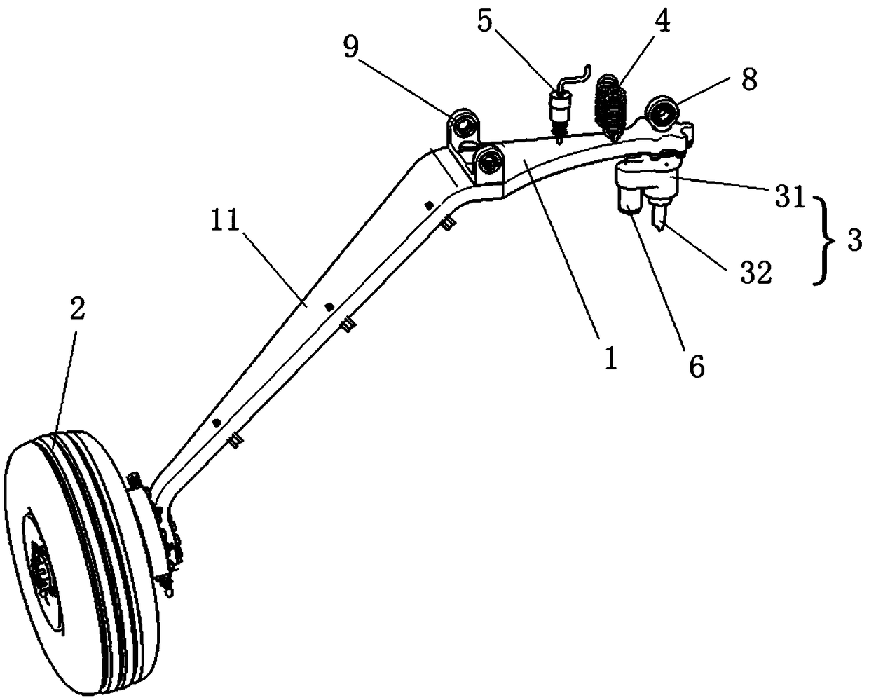
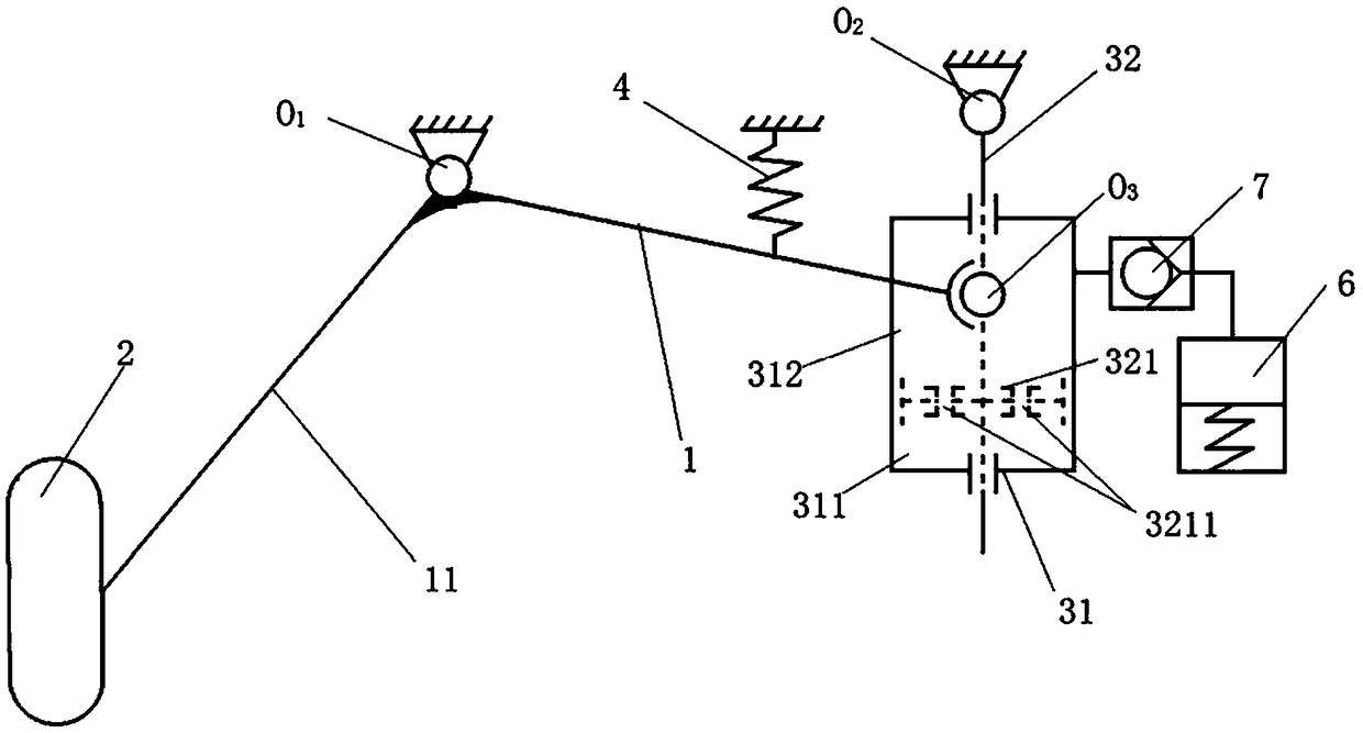
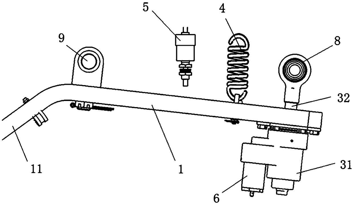
[0049] like figure 1 and figure 2 As shown, the landing gear of this embodiment has a leaf spring 1, a landing gear wheel 2, a spring 4, a wheel load switch 5, a liquid compensation cylinder 6 and a one-way valve 7.

[0050] One end of the leaf spring 1 is bent downward to form a folding arm 11 connecting the landing gear wheel 2, and the middle part of the leaf spring 1 is fixed with a connecting seat 9, and the leaf spring 1 is connected to the fuselage of the aircraft at the first hinge point O through the connecting seat 9. 1 hinged. The other end of leaf spring 1 is provided with buffer 3, and buffer 3 comprises outer cylinder 31 and piston rod 32, and outer cylinder 31 is located at the lower end of leaf spring 1 and is at the third hinge point O with leaf spring 1. 3 hinged. Piston rod 32 has one end of piston 321 and stretches in the outer cylinder 31 after passing leaf spring 1, and piston rod 32 runs through outer cylinder 31 and is connected with outer cylinder ...


PUM


Abstract

A landing gear cushioning mechanism and landing gear are disclosed. The cushioning mechanism has a leaf spring, wherein one end of the leaf spring is bent downward to form a folding arm for connectingthe landing gear wheels, the middle part of the leaf spring is articulated with the fuselage of the aircraft at the first hinge point, the other end of the leaf spring is provided with a buffer, thebuffer comprises an outer cylinder and a piston rod, the outer cylinder is arranged at the lower end of the leaf spring, the piston rod has one end of a piston protruding into the outer cylinder afterpassing through the leaf spring, and the other end of the piston rod is articulated with the fuselage of the aircraft at the second hinge point. The piston divides the inner cavity of the outer cylinder into an upper sealing cavity and a lower sealing cavity, and the piston is provided with a damping hole penetrating in the axial direction, and the inner cavity of the outer cylinder is filled with liquid. Landing impact energy of an aircraft is absorbed under the combined action of a tire, the leaf spring and the buffer. Thus, the aircraft is guaranteed to have high buffering efficiency, theoverload coefficient is reduced, and the landing requirements of the aircraft with large sinking speed and small overload are met.

Description

technical field [0001] The invention belongs to the technical field of aircraft landing devices, in particular to an undercarriage buffer mechanism and an undercarriage. Background technique [0002] Leaf spring landing gear has the advantages of simple structure, high reliability, low cost and simple maintenance. It has always been favored by small aircraft and small drones. Try to avoid passenger discomfort by overloading the landing. In the field of drones, various precision instruments and equipment are often installed on them, and excessive impact loads will cause adverse effects or even damage the instruments and equipment. Therefore, in order to meet the requirements of aircraft economy, comfort, and low impact, the landing process of the landing gear often requires the characteristics of high sinking speed and small impact overload. [0003] Usually, under the same sinking speed of the aircraft, the overload of the aircraft is mainly adjusted by the deformation of ...

Claims


Application Information

Patent Timeline
Patent Type & Authority Applications(China)
IPC IPC(8): B64C25/62
CPCB64C25/62
Inventor 张威张宏李田囡马驰孙继勇傅碧华
Owner LANDING GEAR ADVANCED MFG
Why Eureka
Try Eureka