Flushing device, control method and intelligent toilet cover plate

A technology for controlling mechanisms and moving positions, which is applied in water supply devices, flushing equipment with water tanks, buildings, etc., can solve problems affecting the service life of motors, motor damage, etc., and achieve the goals of prolonging service life, wide application range, and saving water resources Effect

Pending Publication Date: 2019-01-15
XIAMEN R&T PLUMBING TECH
View PDF0 Cites 2 Cited by
  • Summary
  • Abstract
  • Description
  • Claims
  • Application Information

AI Technical Summary

Problems solved by technology

However, the existing motor flushing device drives the drainage mechanism through the rotation of the motor, and forms a stall at the end of the stroke to realize the flushing action; although it overcomes the defects of the mechanical flushing structure, the process of the motor driving the drainage mechanism is not controlled. It is easy to damage the motor and affect the service life of the motor

Method used


Image

  • Flushing device, control method and intelligent toilet cover plate
  • Flushing device, control method and intelligent toilet cover plate
  • Flushing device, control method and intelligent toilet cover plate

Examples


no. 1 example

[0045] The first embodiment (the position detection device adopts the combination of the infrared detection device and the blocking sheet)

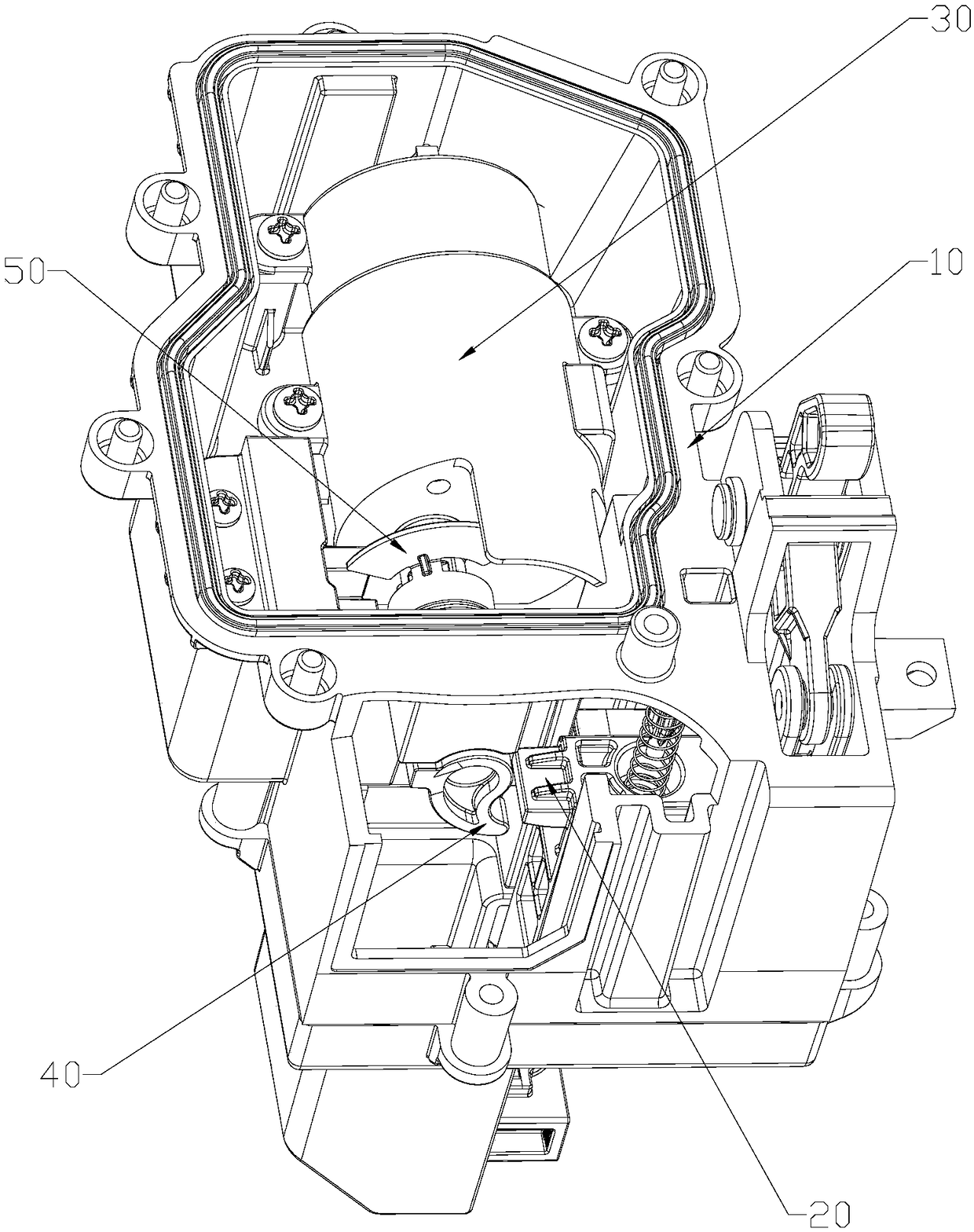
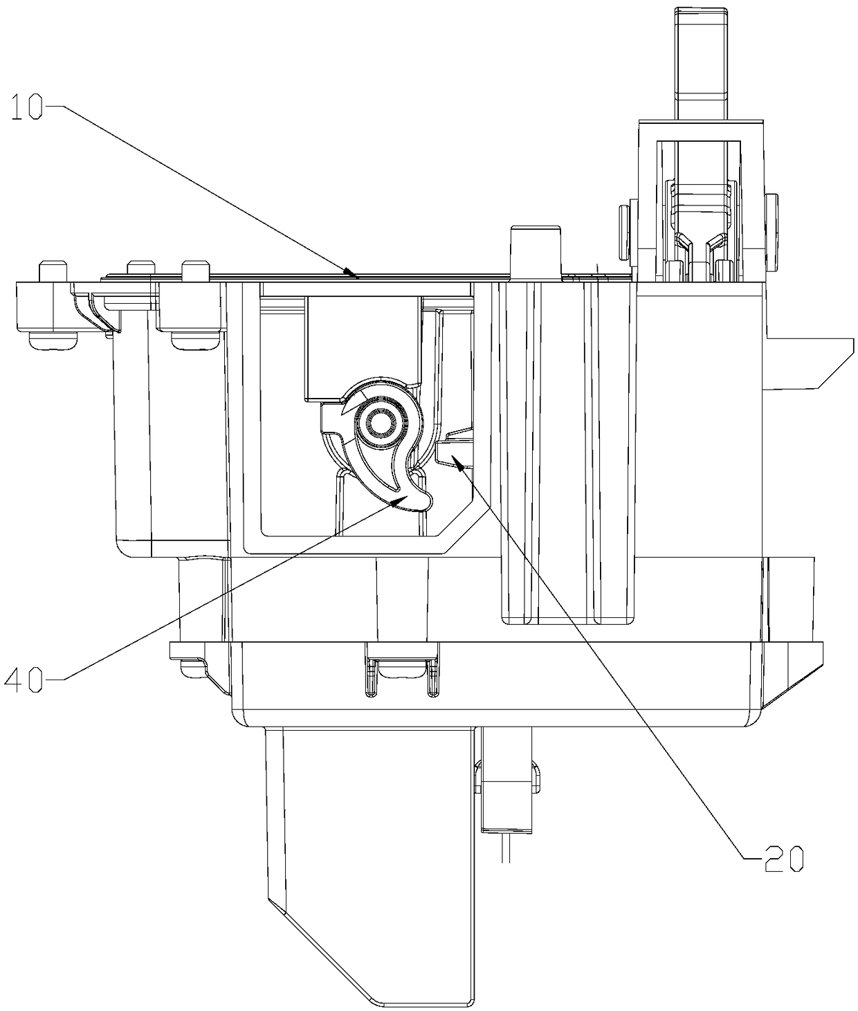
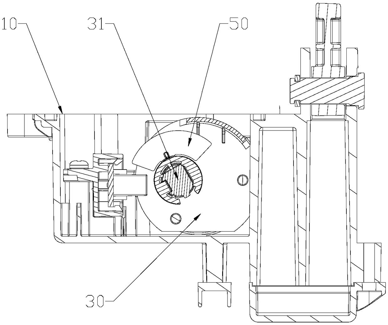
[0046] Such as figure 1 As shown, in this embodiment, the position detection mechanism includes a transmitting tube for emitting light signals and a receiving tube for receiving light signals, and also includes a motor shaft 31 arranged on the driving motor 30 and moving with the driving motor 30 The shielding sheet 50; such as Figure 4 and Figure 5 As shown, when the blocking sheet 50 moves to the blocking position between the transmitting tube and the receiving tube, the optical signal is blocked and converted into a first level signal; as figure 2 and image 3 as shown, or as Figure 6 and Figure 7 As shown, when there is no block between the transmitting tube and the receiving tube, the optical signal is converted into a second level signal; the position detection mechanism is based on the second level signal and the first el...

no. 2 example

[0052] The second embodiment (the position detection mechanism adopts a potentiometer)

[0053] In this embodiment, the position detection mechanism adopts a potentiometer, and the potentiometer outputs different voltage values ​​at different positions, and the main controller reads the voltage value to control the drive motor 30; the potentiometer and the The drainage starting parts 40 are all linked with the drive motor 30; the potentiometer outputs different voltage values ​​at different positions, and the movement position of the drainage starting part 40 is judged according to the voltage value of the potentiometer, and the control mechanism controls The driving motor 30 correspondingly performs forward rotation, stop, and reverse rotation; the driving motor 30 drives the drainage starting member 40 to move forward to the drainage position and drives the drainage mechanism 20 to start drainage; the potentiometer detects When the drainage starting part 40 is at the drainag...


PUM


Abstract

The invention discloses a flushing device, a control method and an intelligent toilet cover plate. The flushing device comprises a main body, a drainage mechanism and a driving motor. The drainage mechanism and the driving motor are mounted on the main body, and the driving motor and the drainage mechanism are driven to start drainage. The device further comprises a control mechanism, a drainage actuator movably disposed between the drive motor and the drainage mechanism, and a position detection mechanism for detecting a moving position of the drainage actuator. The driving motor drives the drainage mechanism through the drainage starter, the position detection mechanism feeds back the position signal to the control mechanism according to the movement position of the drainage starter, andthen the corresponding position signal of the driving motor is controlled to rotate or stop by the control mechanism, thereby realizing the control of the drainage process; Furthermore, the flushingdevice of the present invention can effectively monitor the drainage process by stopping the driving motor at the drainage position when judging the drainage position at the end of the control stroke,thereby solving the problem that the motor is easy to be damaged when the motor is blocked and rotating, thereby prolonging the service life of the motor.

Description

technical field [0001] The invention relates to a flushing device, a control method and an intelligent toilet cover. Background technique [0002] The traditional toilet structure mainly arranges a water tank with a flush button at the rear of the toilet, and forms a water storage area inside the toilet and is connected with a sewage pipe. The flushing button device is installed on the toilet water tank cover, and the push rod at the lower end of the flushing button device and the sealing assembly in the water tank. When flushing, pressing the flushing button drives the sealing assembly to open the drain port for flushing, so that the sewage and dirt in the toilet can be discharged through the sewage pipe to achieve the effect of flushing the toilet. However, the above-mentioned traditional toilet flushing structures all adopt linkage cooperation of mechanical structures, which are not only complicated in structure, difficult in maintenance, and low in service life, but als...

Claims


Application Information

Patent Timeline
Patent Type & Authority Applications(China)
IPC IPC(8): E03D5/04E03D5/10
CPCE03D5/04E03D5/10E03D5/105
Inventor 王子刚黄坤杰
Owner XIAMEN R&T PLUMBING TECH
Why Eureka
Try Eureka