Robot-supported flexible arm tunnel boring machine (Robot-TBM) with multiple cutters boring tunnels with arbitrary cross sections
A robotic arm and robot technology, applied in tunnels, mining equipment, earth-moving drilling and other directions, can solve the problems of increasing the strength of the equipment, increasing the volume and thickness, wasting manpower and material resources, and achieving the effect of flexible structure and large cross-section conversion range.
- Summary
- Abstract
- Description
- Claims
- Application Information
AI Technical Summary
Problems solved by technology
Method used
Image
Examples
Embodiment 1
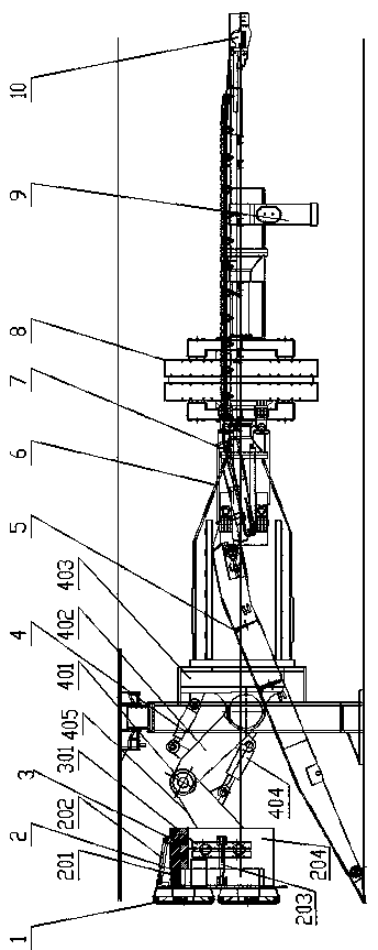
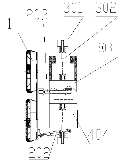
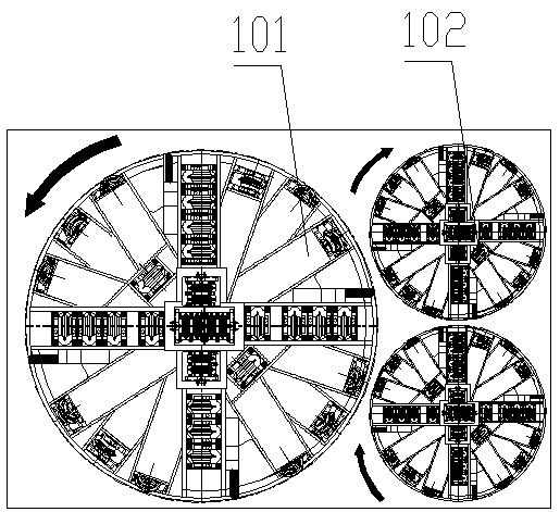
[0039] Such as Figure 1 to Figure 5 As shown, a robot-supported multi-cutterhead flexible-arm tunnel boring machine (Robot-TBM) for excavating tunnels with arbitrary cross-sections includes a main beam 6, and the rear part of the main beam 6 is forwarded by a propulsion cylinder 7 and a rear support shoe 8. The rear part of the rear support shoe 8 is connected with the rear support 9; it is characterized in that: the front part of the main beam 6 is flexibly connected with the cutterhead tool system 1 through the robot 4, and the cutterhead tool system 1 includes at least three cutterhead.
[0040] The front portion of the robot 4 is provided with an anti-cutter torque support shoe system 3 .
[0041]The robot 4 includes a cutterhead attitude adjustment mechanism 2 and a robot arm, the cutterhead cutter system 1 is arranged side by side on the cutterhead attitude adjustment mechanism 2, and the robot arm at the rear of the cutterhead attitude adjustment mechanism 2 is connec...
Embodiment 2
[0045] Such as Image 6 As shown, the robot arm described in the present invention is a serial robot arm 40 . The series robot arm 40 includes a machine arm 402, a machine arm 405 and a rotary base 403, the rotary base 403 is arranged on the main beam 6, the front end of the robot arm 405 is fixedly connected with the connecting seat 204, and the machine arm 402 rear end Through the articulated connection between the kinematic joint 401 and the rotary base 403, the large arm 402 of the machine is articulated with the small arm 405 of the machine; There is a telescopic oil cylinder 404. The tandem robot arm 4 is the mechanical arm body of the tandem robot, wherein the robot arm 401 is the main force-bearing mechanism, the telescopic oil cylinder 402 is used to realize the movement of the robot arm, the kinematic joint 404 is the rotation joint of the robot, and the rotary base 403 is fixed on the main beam The rotary motion of the robot can be realized on the robot, and the m...
Embodiment 3
[0047] Such as Figure 7 and Figure 8 As shown, the robot arm of the present invention is a series-parallel robot arm 42, and the series-parallel robot arm 42 includes a revolving frame 421, a moving frame 422, and a slide rail 423, and the revolving frame 421 is arranged on the top of the moving frame 422, and the moving frame One side of 422 cooperates with slide rail 423, and slide rail 423 is arranged on the main beam 6; Described slewing frame 421 is provided with No. 1 oil cylinder 425 and No. 3 oil cylinder 428 in parallel, and No. 1 oil cylinder 425 is connected with No. 2 oil cylinder through serial joint I426. The oil cylinders 427 are connected in series, and the No. 3 oil cylinder 428 is connected in series with the No. 4 oil cylinder 420 through the series joint II429; the No. 2 oil cylinder 427 and the No. 4 oil cylinder 420 are connected with the cutter head attitude adjustment mechanism 2 through the connecting seat 204. The moving frame 422 is driven by a dr...
PUM
 Abstract
Description
Claims
Application Information
 - R&D
- Intellectual Property
- Life Sciences
- Materials
- Tech Scout
- Unparalleled Data Quality
- Higher Quality Content
- 60% Fewer Hallucinations
Browse by: Latest US Patents, China's latest patents, Technical Efficacy Thesaurus, Application Domain, Technology Topic, Popular Technical Reports.
© 2025 PatSnap. All rights reserved.Legal|Privacy policy|Modern Slavery Act Transparency Statement|Sitemap|About US| Contact US: help@patsnap.com


