
Method, system and apparatus for obtaining residual orbital lifetime of space object in low earth orbit

A space object and low-Earth orbit technology, applied in computer-aided design, design optimization/simulation, special data processing applications, etc., can solve problems such as incomplete burning, landing on the ground, slow calculation speed, etc., and reach low-Earth orbit The effect of fast remaining orbital life of space objects

Active Publication Date: 2019-01-15
NAT ASTRONOMICAL OBSERVATORIES CHINESE ACAD OF SCI
View PDF14 Cites 2 Cited by
  • Summary
  • Abstract
  • Description
  • Claims
  • Application Information

AI Technical Summary

Problems solved by technology

Some in-orbit space objects are mainly affected by atmospheric resistance, and the actual orbit presents a spiral line that is constantly descending, resulting in a gradual decrease in perigee height, and finally causing space objects to fall into the dense atmosphere (100 kilometers above the ground) and burnt. Space objects may not be able to completely burn up in the dense atmosphere, and thus land on the ground, causing harm to the safety of people and property on the ground
[0003] Compared with the actual observation data, the traditional calculation of the remaining orbital life of space objects in low-Earth orbit has a large gap, and the obtained orbital life is not accurate enough and the calculation speed is slow

Method used


Image

  • Method, system and apparatus for obtaining residual orbital lifetime of space object in low earth orbit
  • Method, system and apparatus for obtaining residual orbital lifetime of space object in low earth orbit
  • Method, system and apparatus for obtaining residual orbital lifetime of space object in low earth orbit

Examples


Embodiment Construction

[0045] In order to make the object, technical solution and advantages of the present invention clearer, the present invention will be further described in detail below in conjunction with the accompanying drawings and embodiments. It should be understood that the specific embodiments described here are only used to explain the present invention, not to limit the present invention.

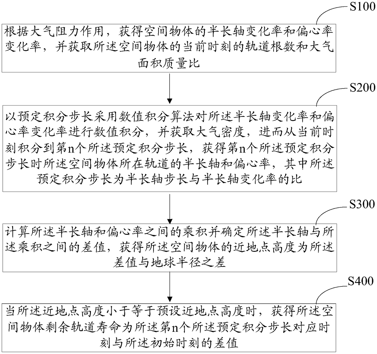
[0046] figure 1 It is a flow chart of a method for obtaining the remaining orbital lifetime of a space object in low-Earth orbit according to an embodiment, and the method includes:

[0047] Step S100, according to the effect of atmospheric drag, obtain the semi-major axis change rate and eccentricity change rate of the space object, and obtain the orbital elements and the atmosphere area-to-mass ratio of the space object at the initial moment.

[0048] Specifically, according to the effect of atmospheric drag, the rate of change of the semi-major axis and the rate of change of the eccentricity of t...


PUM


Abstract

A method for obtaining the residual orbital lifetime of a space object in a low earth orbit include obtaining a semi-major axis change rate, an eccentricity change rate, an orbital element number at acurrent time and an atmospheric area mass ratio of the space object according to an atmospheric drag action; using a numerical integration algorithm to numerically integrate the rate of change of thesemi-major axis and the rate of change of the eccentricity with a predetermined integration step size, and obtaining the atmospheric density, and further integrating to the nth predetermined integration step from the current time to obtain the semi-major axis and the eccentricity of the orbit of the space object when the nth predetermined integration step is taken, wherein the predetermined integration step is the ratio of the semi-major axis step to the semi-major axis change rate; calculating the product of the semi-major axis and the eccentricity and determining the difference between thesemi-major axis and the product to obtain the difference between the perigee altitude of the space object and the radius of the earth; when the perigee height is less than the preset perigee height, obtaining the difference between the time corresponding to the nth preset integration step and the initial time for the remaining orbital lifetime of the space object.

Description

technical field [0001] The invention relates to the field of orbital dynamics of spacecraft, in particular to a method, system and equipment for obtaining the remaining orbital life of a space object in near-Earth orbit. Background technique [0002] Orbital lifetime refers to the time a space object remains in orbit. It is the time from when a space object enters orbit until it falls. Part of the space objects in orbit are mainly affected by atmospheric resistance, and the actual orbit presents a spiral line that is constantly descending, which leads to a gradual decrease in the height of perigee, and finally causes the space objects to fall into the dense atmosphere (100 kilometers above the ground) and burn. Space objects may not be able to completely burn up in the dense atmosphere, and thus land on the ground, causing harm to the safety of people and property on the ground. [0003] Compared with the actual observation data, the traditional calculation of the remainin...

Claims


Application Information

Patent Timeline
Patent Type & Authority Applications(China)
IPC IPC(8): G06F17/50
CPCG06F2119/04G06F30/20
Inventor 张耀吴相彬李大卫刘静
Owner NAT ASTRONOMICAL OBSERVATORIES CHINESE ACAD OF SCI
Learn More