
Anti-delamination semiconductor device and associated method

A semiconductor and anti-delamination technology, used in semiconductor devices, semiconductor/solid-state device components, radiation control devices, etc., and can solve problems such as inoperability of image sensors

Active Publication Date: 2022-05-06
OMNIVISION TECH INC
View PDF4 Cites 0 Cited by
  • Summary
  • Abstract
  • Description
  • Claims
  • Application Information

AI Technical Summary

Problems solved by technology

This wafer-level delamination typically renders one or more of the wafer's image sensors inoperable

Method used


Image

  • Anti-delamination semiconductor device and associated method
  • Anti-delamination semiconductor device and associated method
  • Anti-delamination semiconductor device and associated method

Examples


Embodiment Construction

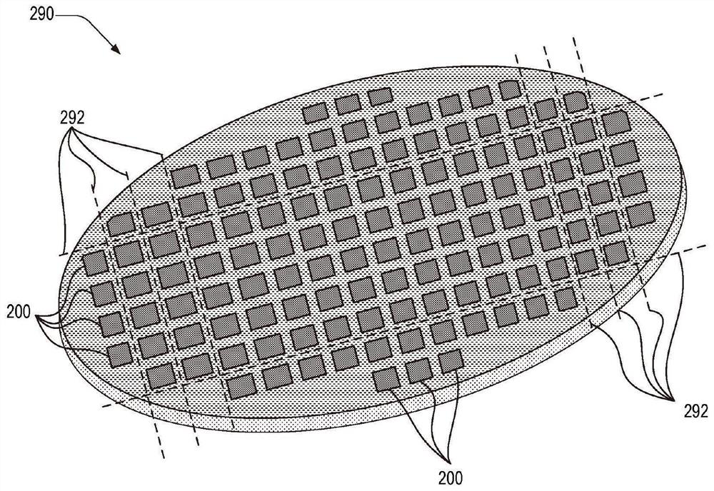
[0036] figure 1 A camera 190 is depicted imaging the scene. Camera 190 includes image sensor 100 having pixel array 102 . figure 2 is a perspective view of an image sensor wafer 290 containing a plurality of uncut image sensors 200. The individual image sensors 100 may be obtained by dicing the image sensor wafer 290 along the dicing plane 292 .

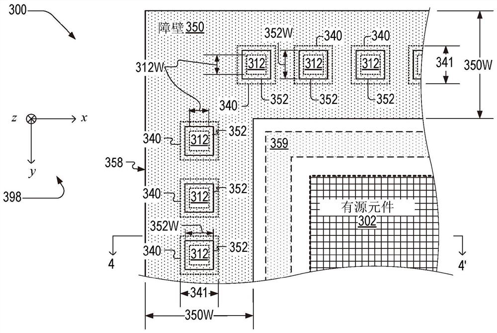
[0037] image 3 and Figure 4 are corresponding cross-sectional views of portions of delamination-resistant semiconductor device 300 . Image sensor 100 is an example of delamination-resistant semiconductor device 300 . image 3 The cross-sectional view is along the Figure 4 3-3' view of the section. Figure 4 The cross-sectional view is along the image 3 4-4' view of the section. Section 3-3' is parallel to the x-y plane and section 4-4' is parallel to the x-z plane with respect to a coordinate system 398 that defines the directions x, y and z. Best observed together in the following instructions image 3 and Figure 4...


PUM

PropertyMeasurementUnit
widthaaaaaaaaaa
thicknessaaaaaaaaaa

Abstract

A delamination-resistant semiconductor device includes a conductive layer, a semiconductor layer, and a spacer. The conductive layer has a first side opposite a second side. The semiconductor layer is on the first side and defines an aperture through the semiconductor layer spanned by the conductive layer. The spacer is on the second side and has a top surface proximate to the conductive layer, the top surface defining a blind via spanned by the conductive layer. A method for preventing delamination of a multilayer structure comprises the step of disposing a first layer on a substrate such that the first layer spans an aperture of the substrate. The method also includes the step of disposing a second layer on the first layer. The second layer has a blind hole adjacent to the first layer such that the first layer spans the blind hole.

Description

technical field [0001] The present invention relates to the field of semiconductor technology, and in particular, to a delamination-resistant semiconductor device and an associated method. Background technique [0002] Mobile devices, motor vehicles, and other consumer electronics typically contain at least one camera. Cameras contain image sensors that are fabricated through a wafer-level manufacturing process using hundreds of additional identical image sensors on a single image sensor wafer. Image sensor wafers have several layers, some of which are prone to delamination during fabrication. Such wafer-level delamination typically renders one or more of the wafer's image sensors inoperable. SUMMARY OF THE INVENTION [0003] Embodiments of the first aspect of the present invention provide a delamination-resistant semiconductor device, comprising: [0004] a conductive layer having a first side opposite the second side; [0005] a semiconductor layer on the first side ...

Claims


Application Information

Patent Timeline
Patent Type & Authority Patents(China)
IPC IPC(8): H01L27/146
CPCH01L27/14632H01L27/14687H01L23/562
Inventor 郭盈志钟莹
Owner OMNIVISION TECH INC
Learn More