A switching control circuit and method, and a switching power supply system

A switch control circuit and switch control technology, applied in the control/regulation system, electrical components, regulating electrical variables, etc., can solve the problems of large input voltage changes, prolonged blanking time, switch conduction point triggering, and output loss of control. , to avoid the effect of switching cycle mutation

Pending Publication Date: 2019-01-15
SHENZHEN KIWI MICROELECTRONICS CO LTD
View PDF10 Cites 1 Cited by
  • Summary
  • Abstract
  • Description
  • Claims
  • Application Information

AI Technical Summary

Problems solved by technology

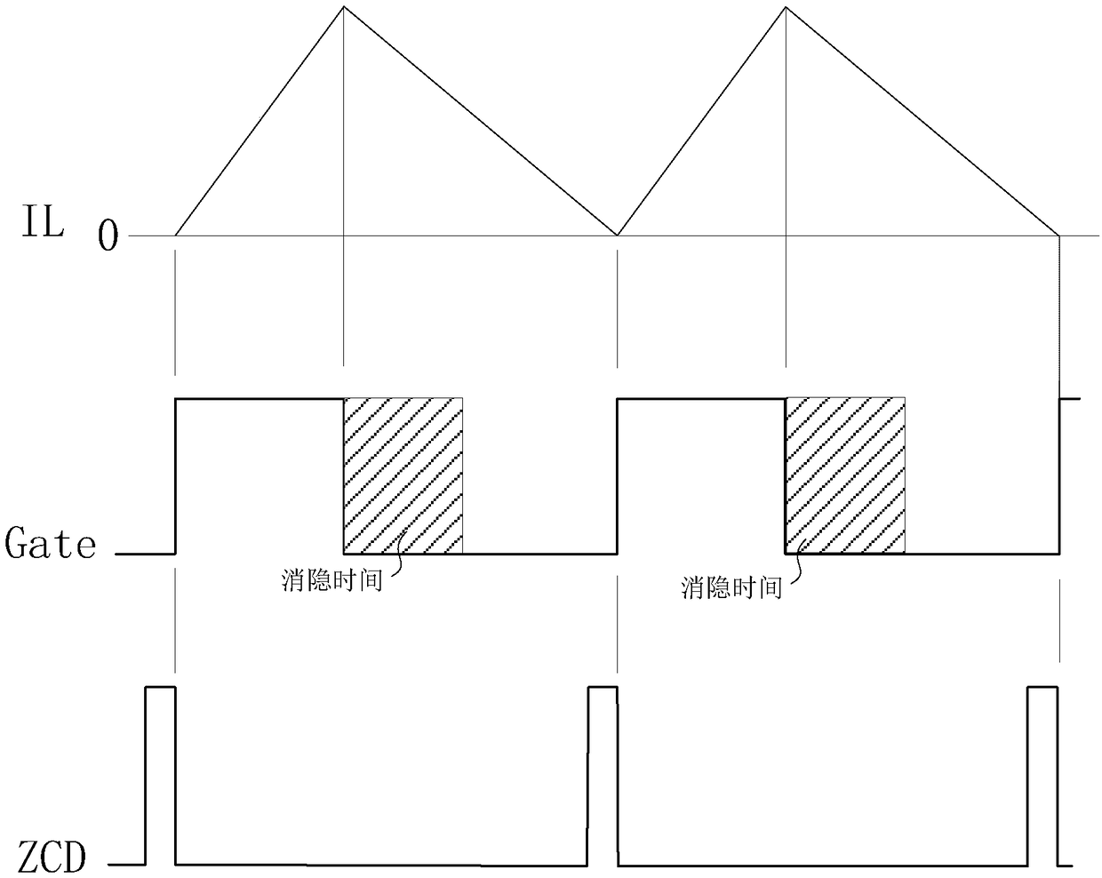
However, when there is interference in the system, especially for the topology of the isolated flyback power supply, or when there is mutual interference between multiple power supplies in parallel, or when the input voltage changes greatly, by setting a fixed blanking time in many cases ( For example, when the frequency is too low) often can not play a good role
[0005] It can be seen that the adaptability of the existing switch control circuit is not strong, and it cannot be applied to many different occasions.
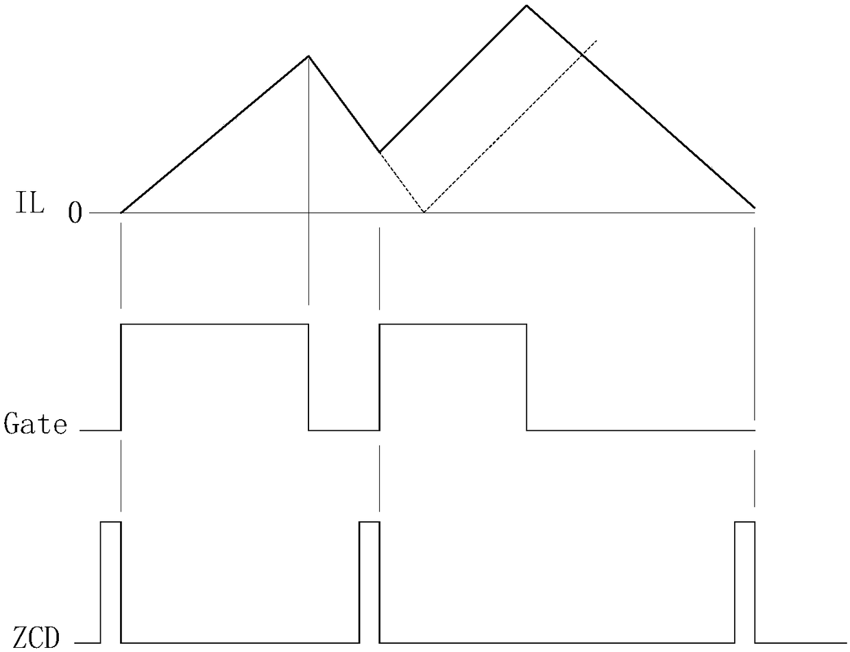
For example, in the occasions of different input and output voltages, or some occasions with interference, if the inductor current drops for a long period, the blanking time may be too short, and it is impossible to avoid entering the CCM mode when the current is large, causing the output to lose control.
For occasions where the inductor current falling phase is short, the short blanking time will prolong the triggering of the switch conduction point, deteriorating the system performance
[0006] In addition, the existing switch control circuit also has similar problems in the complex working environment of the system (such as when the system EMC interference is strong or when multiple power supplies are connected in parallel). When) often cannot play a role in the early stage after shutdown, so that it enters the CCM mode in the early stage, so that the output is out of control

Method used


Image

  • A switching control circuit and method, and a switching power supply system
  • A switching control circuit and method, and a switching power supply system
  • A switching control circuit and method, and a switching power supply system

Examples


Embodiment Construction

[0052] Preferred embodiments of the present invention will be described in detail below in conjunction with the accompanying drawings.

[0053] In order to further understand the present invention, the preferred embodiments of the present invention are described below in conjunction with examples, but it should be understood that these descriptions are only to further illustrate the features and advantages of the present invention, rather than limiting the claims of the present invention.

[0054] The description in this part is only for several typical embodiments, and the present invention is not limited to the scope of the description of the embodiments. The mutual replacement of the same or similar prior art means and some technical features in the embodiments is also within the scope of the description and protection of the present invention.

[0055] "Coupling" or connection in the specification includes both direct connection and indirect connection, such as connection ...


PUM


Abstract

The invention discloses a switching control circuit and method, and a switching power supply system. The switching control circuit comprises an on-time control circuit, an off-time control circuit anda logic circuit. The logic circuit is used for generating a switch control signal gate according to the output signal of the on-time control circuit and the off-time control circuit, and outputting the switch control signal gate to the switch to control the on-time control circuit and the off-time control circuit to the switch. The logic circuit can output a switch control signal gate for controlling the switch to be turned on only after the switching off time length reaches a predetermined proportion of the switching off time length of the previous cycle. The switch control circuit and method of the invention, Switching power supply system, can make blanking time no longer fixed, can be in different occasions, or when the system is unstable adaptive switch conduction point time, can control the adjacent switching cycle more stable, effectively avoid switching cycle abrupt change and inductor current in the earlier stage into the CCM mode, to achieve stable control of the output.

Description

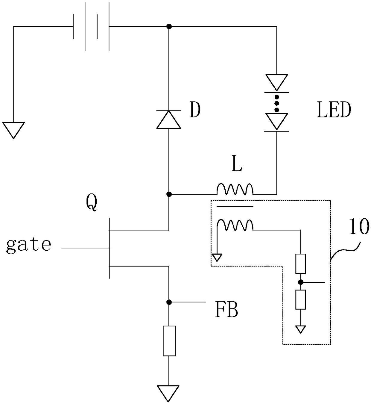
technical field [0001] The invention belongs to the technical field of electronic circuits, and in particular relates to a switch control circuit and method, and a switch power supply system. Background technique [0002] figure 1 It is a schematic diagram of a low-level buck circuit topology. The low-level buck circuit includes a low-level switch Q. By controlling the on and off of the switch Q, the current flowing through the load LED is controlled to drive the LED. When the switch Q is turned on, the power supply, LED, inductor L and switch Q form a current path, and the current rises. When the switch Q is turned off, the LED, the inductor L and the diode D form a current path, and the current drops. Generally, the degaussing detection circuit 10 detects the signal that the current of the inductor L drops to zero value to obtain a ZCD (zero current detection) signal, and when the ZCD signal comes, the switch Q is turned on. When the current flowing through the switch Q...

Claims


Application Information

Patent Timeline
Patent Type & Authority Applications(China)
IPC IPC(8): H02M3/156
CPCH02M3/156
Inventor 张波曾强林官秋
Owner SHENZHEN KIWI MICROELECTRONICS CO LTD
Why Eureka
Try Eureka