Low voltage differential signal transmission device

A signal transmission device, low voltage differential technology, applied in the direction of logic circuit connection/interface layout, electrical digital data processing, logic circuit using specific components, etc., can solve the problem of insurmountable output signal drift, malfunction, deviation from design scope, etc.

Inactive Publication Date: 2003-06-25
VIA TECH INC
View PDF0 Cites 10 Cited by
  • Summary
  • Abstract
  • Description
  • Claims
  • Application Information

AI Technical Summary

Problems solved by technology

[0007] figure 1 , 2 The shortcoming of the known low-voltage differential signal transmission device 102 shown in FIG. signal drift problem
figure 2 The transistor Q5 (for the first current) and the transistors Q6, Q7 (for the second current) will have inconsistent physical characteristics due to process factors during the manufacturing process, and this will make the differential amplifiers provided to the group (Consisting of the transistors Q1~Q4) The current Io used will have a signal drift and does not match the original design specifications
Therefore, the signal swing of the analog video signal S10 output by the group of differential amplifiers will also deviate from the original design range, which will cause subsequent malfunctions of the low-voltage differential signal receiving device 201

Method used


Image

  • Low voltage differential signal transmission device
  • Low voltage differential signal transmission device
  • Low voltage differential signal transmission device

Examples


Embodiment Construction

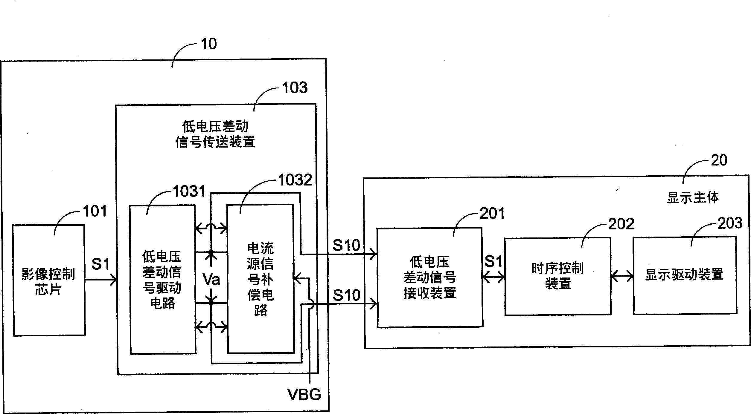
[0047] To further reveal the present invention, please refer to image 3 , Which is a diagram of a preferred embodiment of the low-voltage differential signal transmission device of the present invention; of course, please also refer to it together figure 1 Those shown.

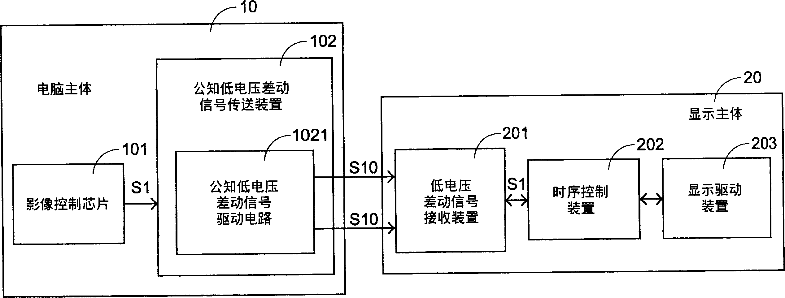
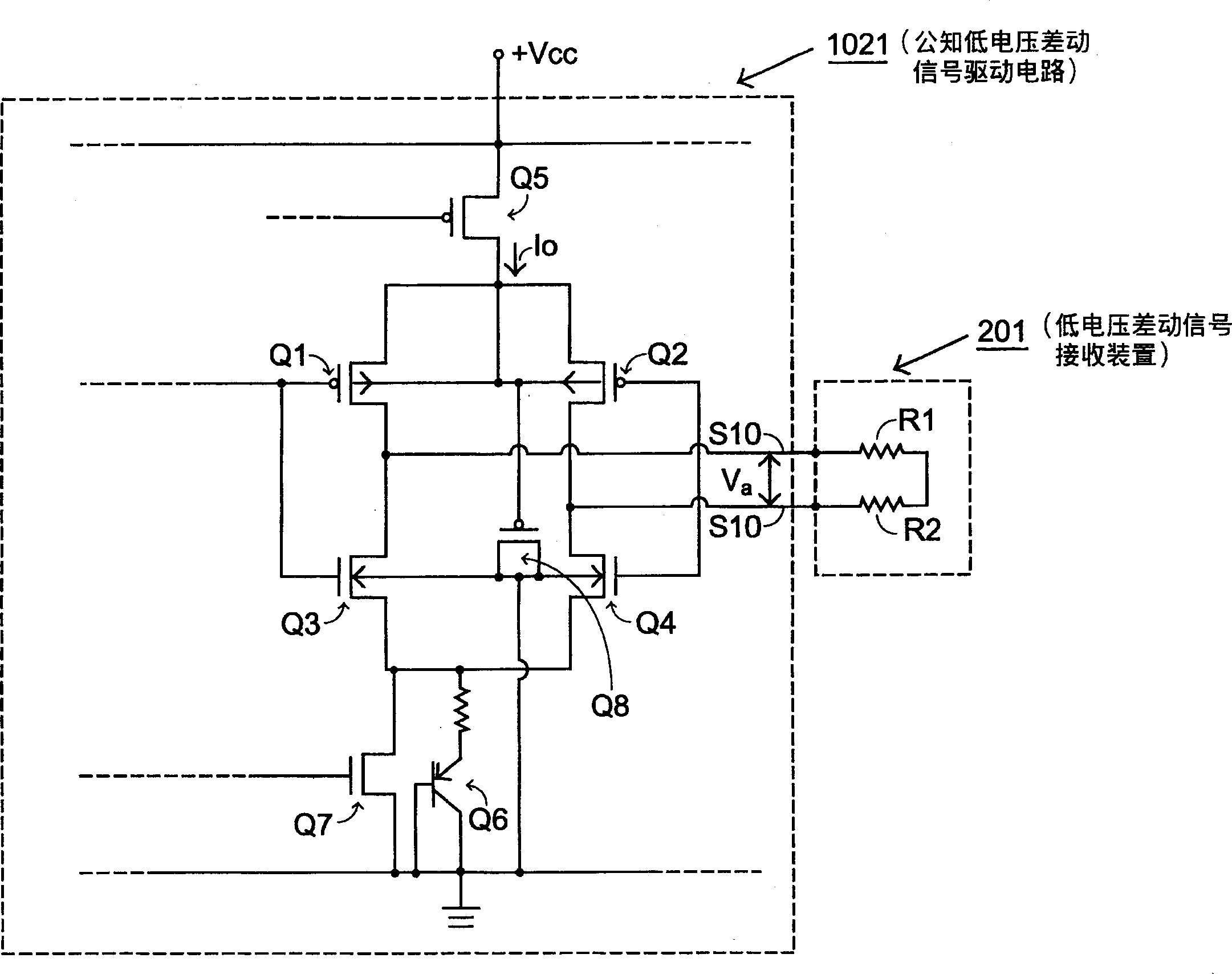
[0048] image 3 The image control chip 101, the display body 20, the digital image signal S1, and the analog image signal S10 in the computer main body 10 shown in FIG. figure 1 As shown, I will not repeat them here. In addition, the computer main body 10 has a low-voltage differential signal transmission device 103, and a low-voltage differential signal drive circuit 1031 with the same function and structure as the known low-voltage differential signal drive circuit 1021 is also provided inside. .

[0049] image 3 versus figure 1 The difference is that a current signal compensation circuit 1032 is also electrically connected to the output terminal of the low-voltage differential signal driving circuit 1031...


PUM


Abstract

This invention relates to a low voltage differential signal transfer device including a signal device circuit for generating and outputting an analog image signal to a low voltage differential signal receiving device and a signal compensation circuit connecting to the said signal drive circuit and generate a feed back compensation signal to the said signal driving circuit with the said analog image signal and a primary standard signal to provide a stabilized said analog image signal to the said low voltage differential signal receiving device, reducing negative influence in signal variation of drive circuit.

Description

Technical field [0001] The invention relates to a low-voltage differential signal transmission device, in particular to a low-voltage differential signal transmission device with the function of feedback and compensation of output signals to provide stable output. Background technique [0002] With the increasing popularity of the Internet, various communication and transmission equipment have become increasingly popular with consumers, and the demand for data transmission has increased rapidly. In addition, digital display video, high-resolution TV and color images all require higher bandwidth to support data streaming. If system design engineers want to transmit large amounts of data, they must rely on analog technology to design circuit systems and support data transmission. Low Voltage Differential Signaling (LVDS) transmission technology is such an analog technology. System design engineers can use this technology to design mixed-signal systems. LVDS uses high-speed analog c...

Claims


Application Information

Patent Timeline
IPC IPC(8): G06F13/38H03K19/003H03K19/0175H03K19/173
Inventor 罗华然林升强陈俊佑居维上
Owner VIA TECH INC
Why Eureka
Try Eureka