An integrated pcb board automatic entry and exit system

A PCB board, integrated technology, applied in the field of integrated PCB board automatic entry and exit systems, can solve the problems of inability to quickly assemble, high defect rate, time-consuming efficiency, etc., and achieve the effect of saving assembly time

Active Publication Date: 2020-10-13
湖南卓芯智能科技有限公司
View PDF4 Cites 0 Cited by
  • Summary
  • Abstract
  • Description
  • Claims
  • Application Information

AI Technical Summary

Problems solved by technology

[0002] The automatic PCB board entry and exit system is a device used to realize the SMT process of the PCB board. At present, the SMT process of many PCB boards, including pasting anti-static sponge pads, still uses manual operation, which is time-consuming and inefficient. Assembling positioning thimbles is still semi-automatic at present. Such an assembly method cannot increase efficiency and has a high defect rate. The existing SMT process cannot be processed well;
[0003] The existing SMT process of PCB boards has certain disadvantages in use. First of all, complex SMT process, sometimes manual assembly is easy to cause defects. If the current semi-automatic method can improve the assembly speed, but different SMT processes on different PCB boards For semi-automatic equipment, different plans must be reserved. Secondly, the two technical processes such as anti-static sponge pad sticking and positioning thimble assembly cannot be realized at the same time. Finally, manual assembly time is wasted, and the SMT process of PCB boards is mostly manual. Or semi-automatic, cannot be assembled quickly, cannot improve assembly efficiency and product quality, and have a certain impact on people's use process. Therefore, we propose an integrated PCB board automatic entry and exit system

Method used


Image

  • An integrated pcb board automatic entry and exit system
  • An integrated pcb board automatic entry and exit system
  • An integrated pcb board automatic entry and exit system

Examples


Embodiment 1

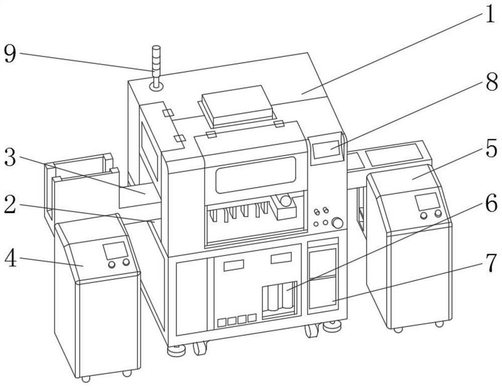
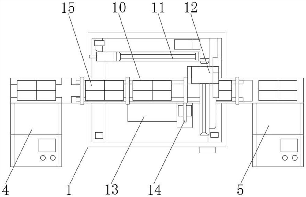
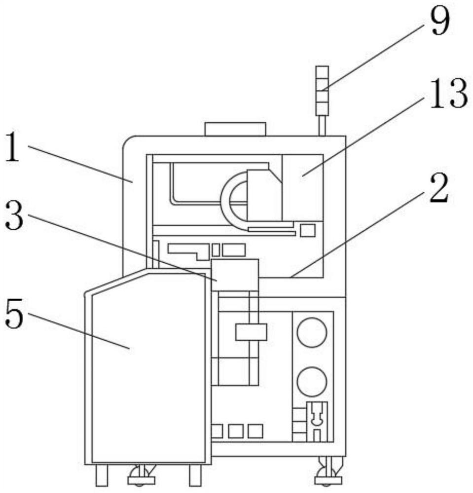
[0022] Such as Figure 1-3 As shown, an integrated PCB board automatic entry and exit system includes a main frame 1, a table panel 2 is provided through the interior of the main frame 1, a timing belt 3 is provided on the upper end of the table panel 2, and a feeding belt is provided at one end of the timing belt 3. Device 4, the other end of the synchronous belt 3 is provided with a receiving device 5, and the inside of the bottom end of the front side of the main box 1 is respectively fixed with an oil-water separator 6 and an industrial computer 7, and the oil-water separator 6 is located on one side of the industrial computer 7 A touch screen 8 is fixedly installed on one side of the upper end of the main chassis 1, a red, yellow and green alarm light 9 is fixedly installed on the outer surface of the upper end of the main chassis 1, and a connecting platform 10 and a cantilevered XY axis 11 are fixedly installed on the upper end of the table panel 2. And the connecting p...

Embodiment 2

[0024] Such as Figure 1-3 As shown, an integrated PCB board automatic entry and exit system includes a main frame 1, a table panel 2 is provided through the interior of the main frame 1, a timing belt 3 is provided on the upper end of the table panel 2, and a feeding belt is provided at one end of the timing belt 3. Device 4, the other end of the synchronous belt 3 is provided with a receiving device 5, and the inside of the bottom end of the front side of the main box 1 is respectively fixed with an oil-water separator 6 and an industrial computer 7, and the oil-water separator 6 is located on one side of the industrial computer 7 A touch screen 8 is fixedly installed on one side of the upper end of the main chassis 1, a red, yellow and green alarm light 9 is fixedly installed on the outer surface of the upper end of the main chassis 1, and a connecting platform 10 and a cantilevered XY axis 11 are fixedly installed on the upper end of the table panel 2. And the connecting p...

Embodiment 3

[0026] Such as Figure 1-3 As shown, an integrated PCB board automatic entry and exit system includes a main frame 1, a table panel 2 is provided through the interior of the main frame 1, a timing belt 3 is provided on the upper end of the table panel 2, and a feeding belt is provided at one end of the timing belt 3. Device 4, the other end of the synchronous belt 3 is provided with a receiving device 5, and the inside of the bottom end of the front side of the main box 1 is respectively fixed with an oil-water separator 6 and an industrial computer 7, and the oil-water separator 6 is located on one side of the industrial computer 7 A touch screen 8 is fixedly installed on one side of the upper end of the main chassis 1, a red, yellow and green alarm light 9 is fixedly installed on the outer surface of the upper end of the main chassis 1, and a connecting platform 10 and a cantilevered XY axis 11 are fixedly installed on the upper end of the table panel 2. And the connecting p...


PUM


Abstract

The invention discloses an integrated PCB automatic access system, comprising a main box, wherein a table panel is arranged through the inside of the main box, a synchronous belt is arranged at the upper end of the table panel, a feeding device is arranged at one end of the synchronous belt, and a receiving device is arranged at the other end of the synchronous belt. The invention relates to the integrated PCB board automatic access system, There are three sets of automatic devices on the machine: a PCB board automatic feeding device, a PCB intelligent access station, a PCB board automatic receiving device. At that same time, the anti-static sponge pad can be adhered, and the positioning thimble can be assembled at the same time; the combined and integrated production line is carried out;a cantilever XY-axis structure is employed and a Z-axis is provided with a CCD detection function, so the manual assembling time is saved. The SMT process of PCB board is automated by machine, whichcan quickly assemble, can improve the assembling efficiency and product quality, and has certain practicability, thus bringing better application prospects.

Description

technical field [0001] The invention relates to the field of SMT technology of PCB boards, in particular to an integrated automatic system for entering and exiting PCB boards. Background technique [0002] The automatic PCB board entry and exit system is a device used to realize the SMT process of the PCB board. At present, the SMT process of many PCB boards, including pasting anti-static sponge pads, still uses manual operation, which is time-consuming and inefficient. Assembling positioning thimbles is still semi-automatic at present. Such an assembly method cannot increase efficiency and has a high defect rate. The existing SMT process cannot be processed well; [0003] The existing SMT process of PCB boards has certain disadvantages in use. First of all, complex SMT process, sometimes manual assembly is easy to cause defects. If the current semi-automatic method can improve the assembly speed, but different SMT processes on different PCB boards For semi-automatic equipm...

Claims


Application Information

Patent Timeline
Patent Type & Authority Patents(China)
IPC IPC(8): H05K13/04
CPCH05K13/0404H05K13/0417
Inventor 蒋黄俊姜胜林赵俊唐文基邓亚雄
Owner 湖南卓芯智能科技有限公司
Why Eureka
Try Eureka