Lower limb exoskeleton robot system based on human-machine terminal interaction

An exoskeleton robot and lower extremity technology, which can be applied to devices that help people move around, physical therapy, etc. The effect of good follow-up effect, accurate human-computer interaction information, and obvious power assist effect

Active Publication Date: 2019-01-18
HARBIN INST OF TECH
View PDF6 Cites 25 Cited by
  • Summary
  • Abstract
  • Description
  • Claims
  • Application Information

AI Technical Summary

Problems solved by technology

[0005] The present invention aims to solve the problems that the existing lower extremity exoskeleton has poor fit to the human body, uncomfortable to wear, and inaccurate human-computer interaction information, resulting in poor human-machine following effect and inconspicuous power-assist effect, and further provides a human-based exoskeleton Lower limb exoskeleton robot system with machine-end interaction

Method used


Image

  • Lower limb exoskeleton robot system based on human-machine terminal interaction
  • Lower limb exoskeleton robot system based on human-machine terminal interaction
  • Lower limb exoskeleton robot system based on human-machine terminal interaction

Examples


specific Embodiment approach 1

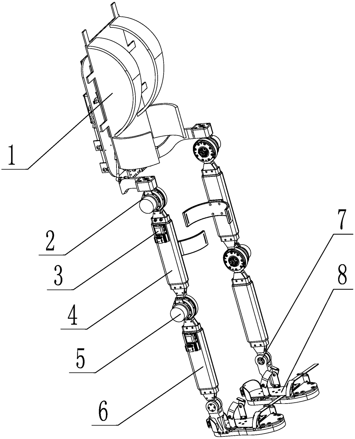
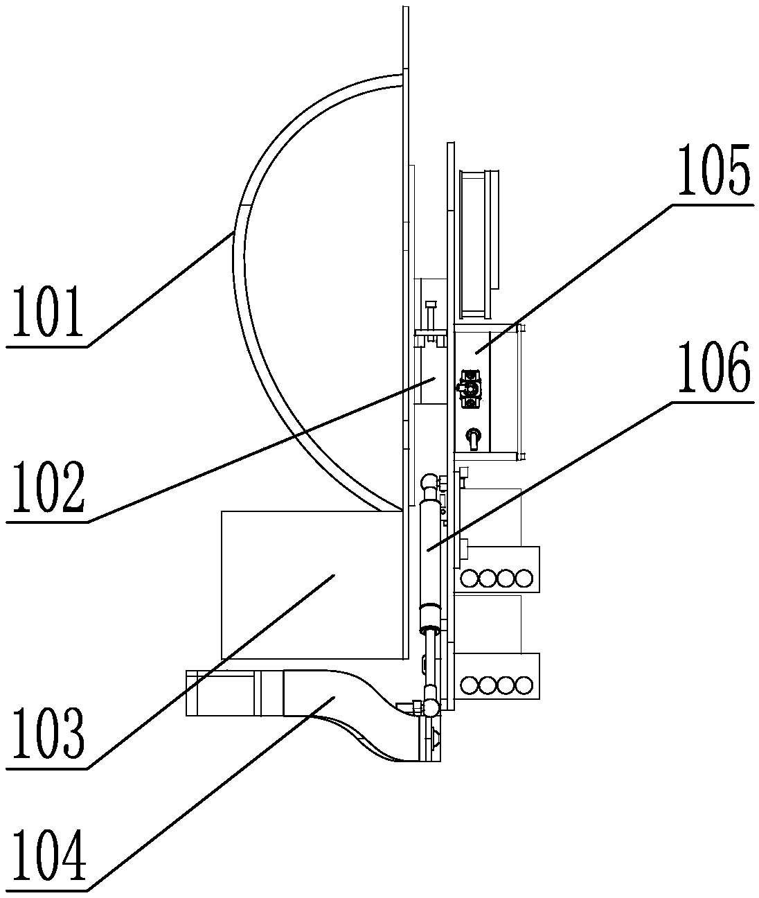
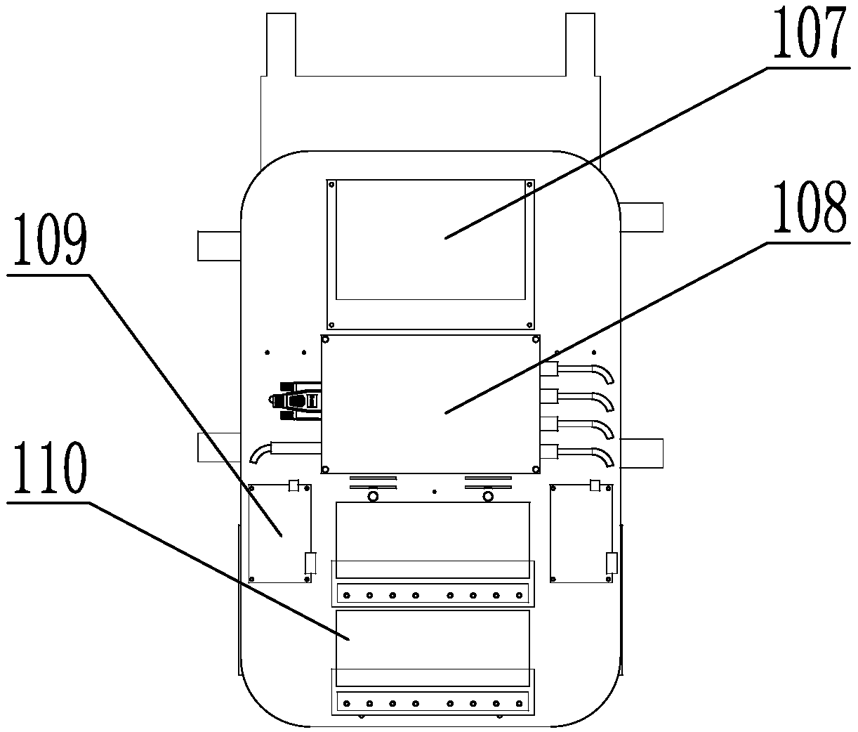
[0032] Specific implementation mode one: as Figure 1-8 As shown, the lower extremity exoskeleton robot system based on human-computer interaction in this embodiment includes a back frame 1, two hip joints 2, two inertial units 3, two thigh bars 4, two knee joints 5, and two lower legs Rod 6, two ankle joints 7 and two plantar pressure shoes 8, two hip joint brackets 104 are symmetrically arranged on the lower part of the back frame 1, and one end of the hip joint bracket 104 connects with the back frame 1 through adduction and abduction shaft 201 Rotationally connected, the free end of each hip joint support 104 is rotationally connected with the corresponding hip joint 2 through the hip internal and external rotation axis 203, and each hip joint 2 is connected with the corresponding thigh rod 4 through the hip flexion and extension axis 202, and each thigh An inertial unit 3 is arranged on the upper part of the bar 4, and the lower part of each thigh bar 4 is connected with ...

specific Embodiment approach 2

[0034] Specific implementation mode two: as Figure 8 and Figure 9 As shown, the first link assembly of the telecentric mechanism in this embodiment includes a first link 705, a second link 706, and two first connecting pieces 708, and the first link 705 is parallel to and opposite to the second link 706. , the length of the first connecting rod 705 is less than the length of the second connecting rod 706, and one end of the first connecting rod 705 and the second connecting rod 706 are rotatably connected with the ankle joint connector 703 through a connecting shaft 711, the first connecting rod 705 The other end of the second connecting rod 706 is connected with the middle part of the second connecting rod 706 through two first connecting pieces 708 and two connecting shafts 711; the second connecting rod assembly of the telecentric mechanism includes the third connecting rod 707, the fourth connecting rod 710 and two A second connecting piece 709, the third connecting rod...

specific Embodiment approach 3

[0036] Specific implementation mode three: as Figure 5 As shown, the knee joint 5 in this embodiment includes a motor 501, a fixed cover 502, a harmonic reducer 503, a connecting plate 504, a knee joint body, a thigh rod connector 505, a calf rod connector 507, and a reducer output shaft 508. The lower end of the rod connector 505 is provided with an outer edge, the fixed cover 502 and the connecting plate 504 are arranged in parallel and fixed on the outer edge of the thigh rod connector 505, the motor 501 is fixed on one end surface of the fixed cover 502, and the harmonic deceleration One end of the device 503 is fixed on the other end surface of the fixed cover 502, the other end of the harmonic reducer 503 is connected with the connecting plate 504, the output shaft 508 of the reducer is fixed on the harmonic reducer 503, and the knee joint body passes through the deep The groove ball bearing 506 is installed on the output shaft 508 of the reducer, and the upper end of t...


PUM


Abstract

The invention provides a lower limb exoskeleton robot system based on human-machine terminal interaction, and relates to a lower limb exoskeleton robot. The system solves the problems of poor adhesionbetween the lower limb exoskeleton and the human body, uncomfortable wearing, inaccurate human-computer interaction information, poor man-machine following effect and inconspicuous power assisting effect caused by the prior lower limb exoskeleton. A low part of that back frame is symmetrically provided with two hip joint bracket, one end of the hip joint support is rotatably connected with the back frame 1 through an adduction and abduction shaft, the free end of each hip joint bracket is rotatably connected to the corresponding hip joint through an internal and external hip rotation axis, Each hip joint is connected with a corresponding thigh rod through a hip flexion and extension shaft, an inertia unit is arranged at the upper part of each thigh rod, the lower part of each thigh rod isconnected with the upper end of the corresponding calf rod through a knee joint, one end of a pneumatic spring is connected with a back frame, and the other end of the pneumatic spring is connected with a corresponding hip joint bracket. The invention is used for a lower limb exoskeleton robot.

Description

technical field [0001] The invention relates to a lower limb exoskeleton robot, in particular to a lower limb exoskeleton robot system based on human-machine terminal interaction. Background technique [0002] An exoskeleton robot is a wearable device that integrates various technologies such as sensing technology and control technology. In particular, a lower limb exoskeleton robot is an exoskeleton robot that is similar in structure to the lower limbs of a human body, and can help the wearer realize Assist walking, lower limb rehabilitation, up and down stairs and other actions. [0003] The lower extremity exoskeleton robot is mainly composed of hip joints, knee joints and ankle joints, with 15 degrees of freedom, including waist rotation, hip extension and flexion, hip abduction, hip internal and external rotation, knee extension and flexion, ankle extension and flexion, Ankle rotation, ankle inversion. [0004] At present, the existing lower extremity exoskeleton has ...

Claims


Application Information

Patent Timeline
Patent Type & Authority Applications(China)
IPC IPC(8): A61H3/00
CPCA61H3/00A61H2003/005A61H2003/007A61H2201/1207A61H2201/165A61H2201/1659
Inventor 董为陈朝峰杜志江毛薇
Owner HARBIN INST OF TECH
Why Eureka
Try Eureka