
Electrolytic copper foil additive heating insulation system

A technology of heating and heat preservation and electrolytic copper foil, which is applied in electrolysis process, electrolysis components, electroforming, etc., can solve the problems of high failure rate of heating system, failure of additives, burning of heating rods, etc., and achieve low heat source temperature and stable system High performance and increased safety effect

Inactive Publication Date: 2019-01-18
JIANGDONG ELECTRONIC MATERIALS CO LTD
View PDF11 Cites 2 Cited by
  • Summary
  • Abstract
  • Description
  • Claims
  • Application Information

AI Technical Summary

Problems solved by technology

[0003] 1) When the heating rod is in use, the surface of the heating rod is as high as above 200°C, and some additives fail due to high temperature, and even evolve into impurities in the solution, which affects the quality of the electrolytic copper foil;
[0004] 2) When the heating rod is continuously used in the additive solution, some additives will gradually form organic scale on the surface of the heating rod, and the heat of the heating rod is difficult to radiate and utilize, resulting in burning of the heating rod, resulting in a high failure rate of the heating system, which affects the electrolytic copper. Foil product quality stability

Method used


Image

  • Electrolytic copper foil additive heating insulation system

Examples


Embodiment Construction

[0017] The present invention will be described in further detail below through examples, and the following examples are explanations of the present invention and the present invention is not limited to the following examples.

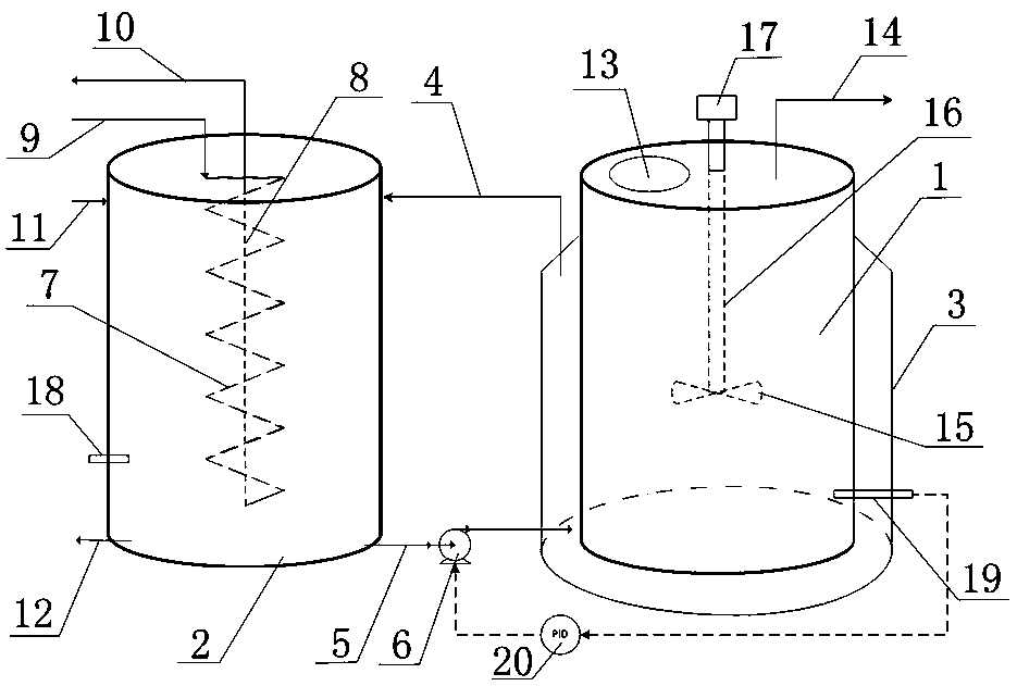
[0018] Such as figure 1 As shown, an electrolytic copper foil additive heating and heat preservation system of the present invention includes an additive tank 1 and a heating tank 2. A heating jacket 3 is arranged on the outside of the additive tank 1. The heating jacket 3 is a cylinder without a cover and the heating jacket 3 The inner diameter is larger than the outer diameter of the additive tank 1, the heating jacket 3 is sleeved on the outside of the additive tank 1 from the lower end of the additive tank 1, the upper end of the heating jacket 3 extends obliquely inward and is sealed and fixed on the outer surface of the additive tank 1, and the inner wall of the heating jacket 3 The gap between the outer wall of the additive tank 1 is a closed hea...


PUM


Abstract

The invention discloses an electrolytic copper foil additive heating insulation system which comprises an additive tank and a heating tank, wherein a heating jacket is arranged on the outer side of the additive tank; the heating jacket is an uncovered cylinder, and the inner diameter of the heating jacket is greater than the outer diameter of the additive tank; the heating jacket is sleeved on theouter side of the additive tank from the lower end of the additive tank; the upper end of the heating jacket inclines and extends toward inner side and is fixedly sealed on the outer side surface ofthe additive tank; a gap between the inner wall of the heating jacket and the outer wall of the additive tank is a closed heating water cavity; the upper end side surface of the heating jacket is communicated with the upper end side surface of the heating tank through a return water pipe; the lower end side surface of the heating jacket is communicated with the lower end side surface of the heating tank through a delivery pipe, and a delivery pump is arranged on the delivery pipe; a heating disc is arranged in the heating tank. According to the system disclosed by the invention, since a heat source does not directly contact with an additive, the safety of the additive is improved, and the system stability is high.

Description

technical field [0001] The invention relates to a heating and heat preservation system, in particular to an electrolytic copper foil additive heating and heat preservation system. Background technique [0002] A variety of organic additives are used in the production process of electrolytic copper foil, which are added to pure water and stirred evenly during use. Some additives need to be heated to 40-70°C, and some additives need to be kept at room temperature (about 25°C). . Therefore, the additive needs to be heated and kept warm. The common heating and heat preservation methods for electrolytic copper foil additives are: using a heating rod to directly contact the solution, and controlling the heating temperature through temperature adjustment. This method has the following defects: [0003] 1) When the heating rod is in use, the surface of the heating rod is as high as above 200°C, and some additives fail due to high temperature, and even evolve into impurities in th...

Claims


Application Information

Patent Timeline
Patent Type & Authority Applications(China)
IPC IPC(8): B01F3/12B01F3/20B01F7/18B01F15/06C25D1/04C25D3/38C25D21/14B01F23/70
CPCC25D1/04C25D3/38C25D21/14B01F23/53B01F23/711B01F27/90B01F2035/99B01F35/92
Inventor 刘诗涛唐海峰张小龙李帅戴智成
Owner JIANGDONG ELECTRONIC MATERIALS CO LTD
Learn More