Construction waste treatment device

A processing device and construction waste technology, applied in grain processing, solid separation, filtering and screening, etc., can solve the problems of unfavorable transportation and recycling, uneven crushing effect, and inability to guarantee the crushing effect, etc., to achieve fast and efficient processing, and convenient Subsequent transportation and recycling, the effect of avoiding clogging

Active Publication Date: 2019-01-18
重庆市安平建筑有限责任公司
View PDF6 Cites 19 Cited by
  • Summary
  • Abstract
  • Description
  • Claims
  • Application Information

AI Technical Summary

Problems solved by technology

[0003] Most of the demolished construction waste exists in the form of blocks, which is inconvenient to transport and needs to be crushed. If it is to be recycled, it needs to be crushed to make it into particles before it can be used; the traditional crushing method is to manually use a drill or drive a drilling rig for crushing. The crushing effect is uneven, and the crushing effect cannot be guaranteed, which is not conducive to transportation and recycling

Method used


Image

  • Construction waste treatment device
  • Construction waste treatment device
  • Construction waste treatment device

Examples


Embodiment 1

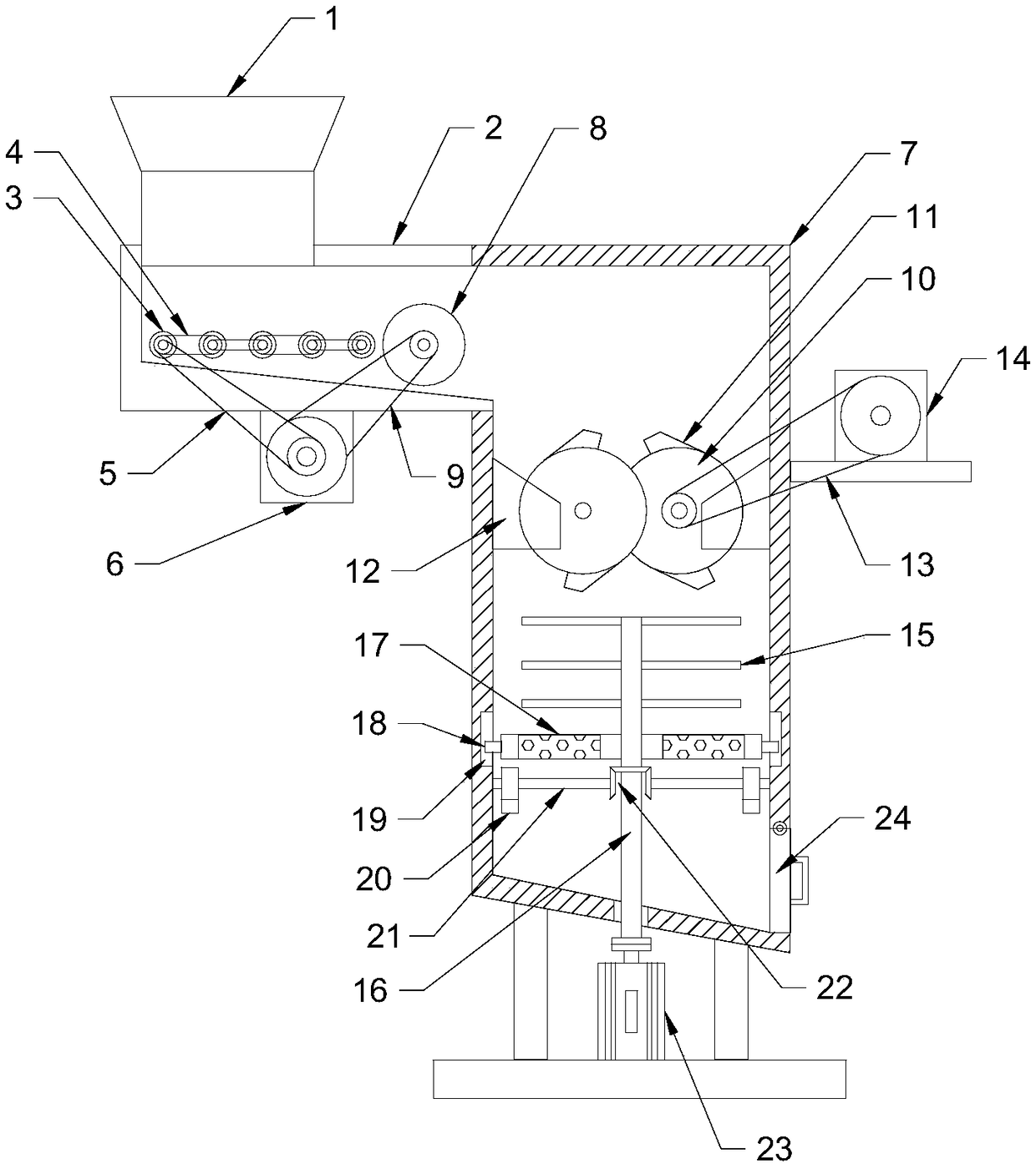
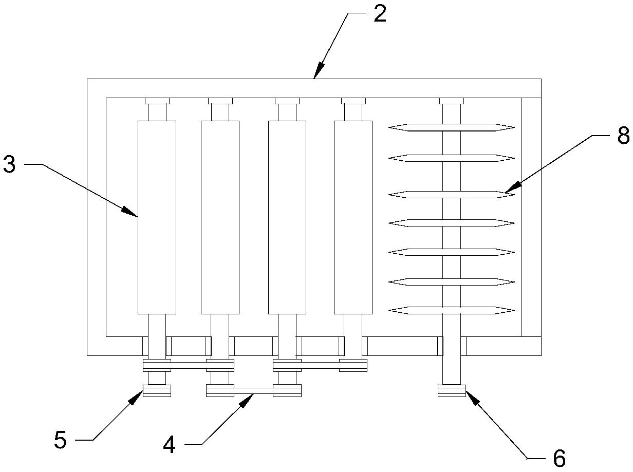
[0023] See Figure 1~3 In the embodiment of the present invention, a construction waste treatment device includes a feeding hopper 1, a feeding box 2 and a crushing box 3. A feeding box 2 is connected below the feeding hopper 1, and the feeding box 2 is provided with equidistant Distributed feeding rollers 3, feeding rollers 3 and the inner wall of the feeding box 2 are connected in rotation, the feeding rollers 3 are connected by a first transmission belt 4, and the end of the feeding roller 3 is connected with a second transmission belt 5 An output shaft of a driving motor 6, the first driving motor 6 is fixedly connected to the lower end surface of the conveying box 2 through bolt-fixed waterproof, the first driving motor 6 drives the conveying roller 3 to rotate to transport the construction waste.

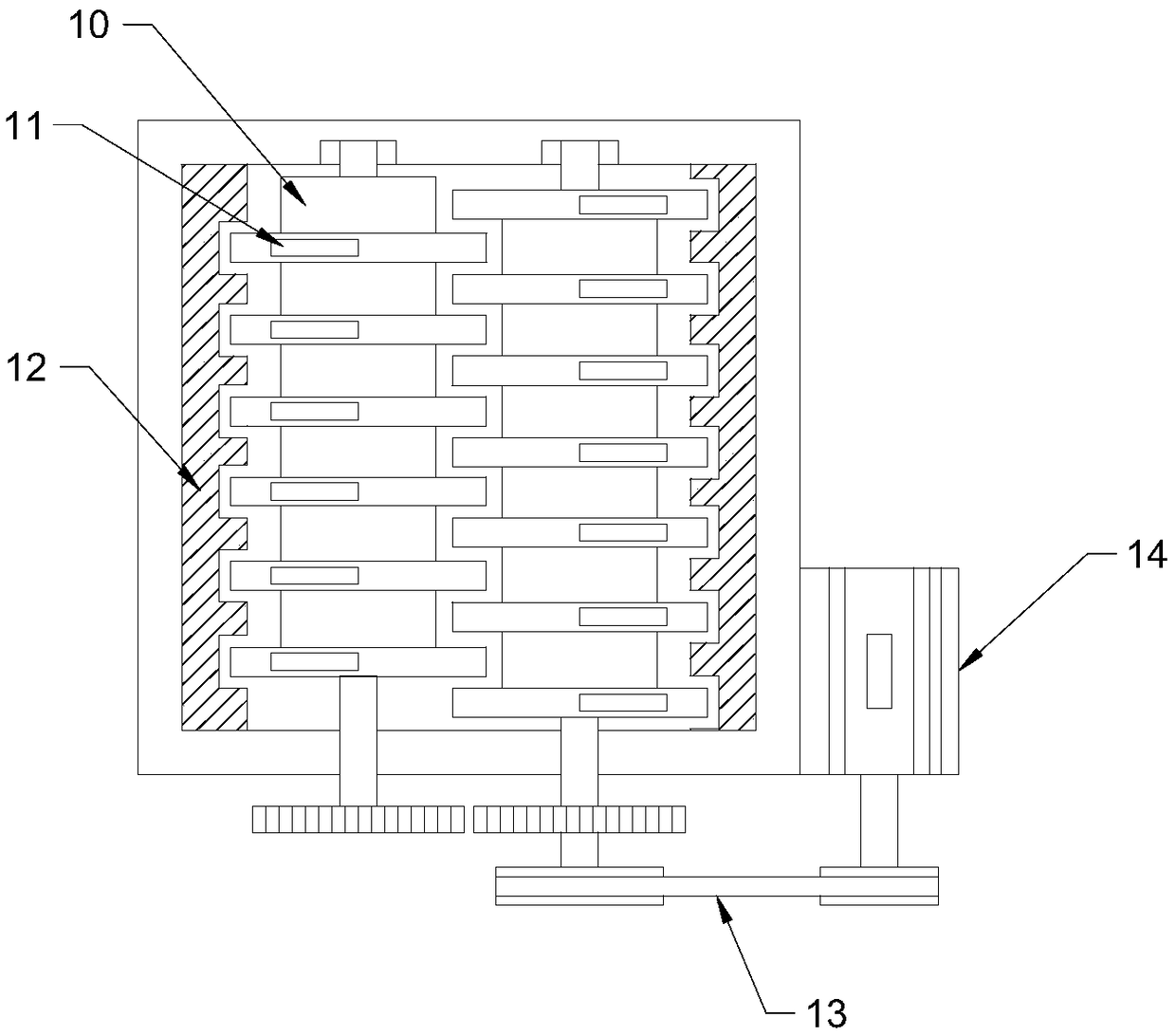
[0024] A crushing box 7 is connected to the right side of the conveying box 2, and a cutting blade roller 8 is provided at the connection between the conveying box 2 and the crus...

Embodiment 2

[0028] See Figure 4 The difference between this embodiment and embodiment 1 is that: the inner wall of the upper end of the crushing box 7 is fixedly connected with a dust collecting cover 25, the dust collecting cover 25 is connected with an induced draft fan 26 through a pipeline, and the induced draft fan 26 is connected with a cyclone settling cylinder 27 through a pipeline. , Actively suck the dust in the crushing process to avoid dust overflow and pollute the working environment.


PUM


Abstract

The invention discloses a construction waste treatment device. The construction waste treatment device comprises a feeding hopper, a material conveying box and a pulverizing box, wherein the lower part of the feeding hopper communicates with the material conveying box; material conveying rollers which are equidistantly distributed are arranged in the material conveying box; the right side of the material conveying box communicates with the pulverizing box; a cutting blade roller is arranged at a communicating part of the material conveying box and the pulverizing box; a squeezing roller groupis arranged in the pulverizing box; a pulverizing cutter is arranged below the squeezing roller group; a sieve plate is arranged below the pulverizing cutter; and a cam is abutted below the sieve plate. Construction waste blocks to be pulverized are cut by the cutting blade roller, and are separated, so that the follow-up crushing is facilitated, and the overall processing efficiency is improved;the sieve plate which vibrates up and down is arranged below the pulverizing cutter, is prevented from being blocked, and meanwhile causes the waste blocks which do not reach the pulverization particle sizes to be in contact with the pulverizing cutter again, and thus, the pulverizing effect is ensured; the rapid and efficient treatment of the waste blocks is realized by cutting, crushing and pulverizing three-stage mechanisms; and the follow-up transportation and recycling are facilitated.

Description

Technical field [0001] The invention relates to the field of construction, in particular to a construction waste treatment device. Background technique [0002] Construction waste is solid waste generated during the construction, reconstruction, expansion or demolition of buildings. According to different sources of construction waste, it can be divided into construction waste and demolished construction waste. As the name suggests, construction waste is solid waste generated in new construction, reconstruction or expansion projects, and demolition of construction waste is construction waste generated during the demolition of buildings. [0003] Most of the demolished construction waste exists in block form, which is inconvenient to transport and needs to be crushed. If it is to be recycled, it needs to be crushed to make it into granules before it can be used. The traditional crushing method is to manually use a drill or drive a drill to crush. The crushing effect is uneven, and...

Claims


Application Information

Patent Timeline
Patent Type & Authority Applications(China)
IPC IPC(8): B02C4/08B02C18/12B02C23/16B07B1/34B26D1/28B26D7/06
CPCB02C4/08B02C18/0092B02C18/12B02C23/16B02C2023/165B02C2201/06B07B1/343B26D1/28B26D7/06
Inventor 渠衍飞
Owner 重庆市安平建筑有限责任公司
Why Eureka
Try Eureka