
A complete set of high concentration flotation machine

A complete set of equipment and flotation machine technology, applied in flotation, solid separation, etc., can solve the problems of flotation machine configuration not reflected, no stirring system, etc.

Active Publication Date: 2020-10-20
BGRIMM MACHINERY & AUTOMATION TECH CO LTD +1
View PDF5 Cites 0 Cited by
  • Summary
  • Abstract
  • Description
  • Claims
  • Application Information

AI Technical Summary

Problems solved by technology

This patent relies on the middling pump to generate the power source to circulate the pulp and to suck the air. There is no stirring system. Although the bottom is a conical tank, it is only used as a pulp channel and does not reflect the configuration of the flotation machine.

Method used


Image

  • A complete set of high concentration flotation machine
  • A complete set of high concentration flotation machine
  • A complete set of high concentration flotation machine

Examples


specific Embodiment

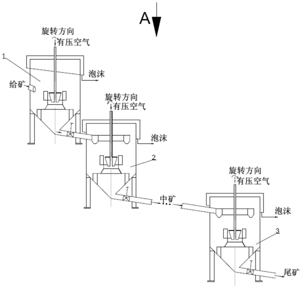
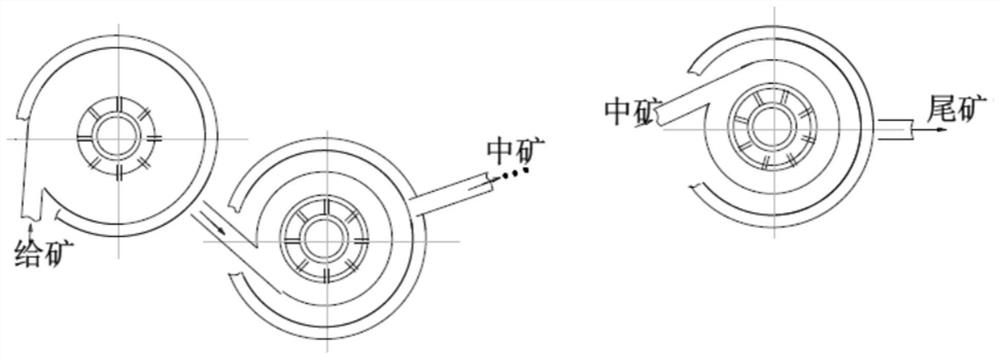
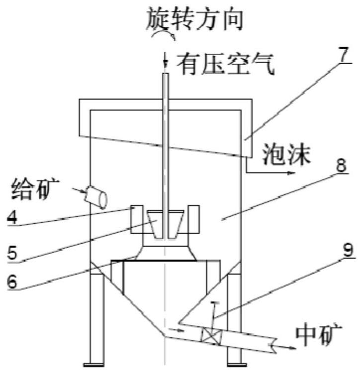
[0042] Such as figure 1 , figure 2 As shown, it includes an ore feeding flotation machine 1, a middle selection flotation machine 2 and a tailing flotation machine 3. Generally, it consists of 1 feeding flotation machine 1, 2-5 flotation machines 2 for middle selection (determined by the flotation time), and 1 tailing flotation machine 3. The fresh ore pulp is generally fed to the side of the inner impeller of the flotation machine along the tangential direction of the ore feeding flotation machine 1, and the bottom flow of the flotation machine for the ore feeding is fed into the slurry distributor of the middle selection flotation machine 2 as the middle ore tangentially. From the bottom of the previous flotation machine, it is tangentially fed into the next intermediate flotation machine, and multiple intermediate flotation machines are arranged tangentially in a staggered direction; the bottom flow of the last intermediate flotation machine is tangentially fed into the t...


PUM


Abstract

The invention discloses a high-concentration flotation machine set. The machine set includes an ore feeding flotation machine, multiple middle flotation machines and a tail floatation machine which are connected with one another in sequence, an ore slurry feeding pipe tangentially feeds ore slurry to the upper portion of the side face of an impeller in the ore feeding flotation machine from a groove body of the ore feeding flotation machine, a bottom flow of the ore feeding flotation machine is adopted as a middling tangent line and fed to the middle flotation machines, a bottom flow of each middle flotation machine is tangentially fed into the next middle flotation machine from the bottom of the previous middle flotation machine, and the bottom flow of the last middle flotation machine istangentially fed into the tail flotation machine from the bottom of the last middle flotation machine. The middle flotation machines are staggered and tangentially distributed for ore feeding; the impeller of the ore feeding flotation machine rotates clockwise; the first connected middle flotation machine rotates counterclockwise, the second middle flotation machine rotates clockwise, and all themiddle flotation machines are sequentially staggered. The flow feeding direction is same as the rotation direction of the impeller, and a bottom flow discharge pipe is radially arranged along the groove body. Under a high-concentration ore feeding condition, effective bubble dispersion, particle suspension, uniform ore distribution, collision between the particles and bubbles, concentration of the ore slurry and the like in one flotation machine are achieved, the purpose of high-concentration sorting is achieved, and the effects of saving water and medicaments, shortening workflow configuration, saving energy and reducing energy consumption are achieved at last.

Description

technical field [0001] The invention relates to a complete set of flotation machines, in particular to a complete set of high-concentration flotation machines. Background technique [0002] 90% of non-ferrous metals and 50% of ferrous metals in the world are processed by flotation. The flotation machine is one of the most important supports to realize the flotation process. The flotation machine is a kind of equipment that uses the difference of hydrophobicity and hydrophilicity of minerals under the condition of gas-liquid-solid three-phase to realize the collision, adhesion, transportation and final recovery of target minerals by air bubbles. It is mainly composed of a driving device, a stirring shaft system, an impeller, a stator and a tank. The flotation machine mainly realizes the suspension of the pulp in the flotation tank, the dispersion of air bubbles and the mineralization of the collision between useful minerals and air bubbles through impeller agitation. [00...

Claims


Application Information

Patent Timeline
Patent Type & Authority Patents(China)
IPC IPC(8): B03D1/14
CPCB03D1/1406
Inventor 张跃军史帅星陈东夏晓鸥董干国赖茂河
Owner BGRIMM MACHINERY & AUTOMATION TECH CO LTD
Learn More