
Reinforcing steel bar slitting machine for building construction

A technology of building construction and slitting machine, which is applied in the direction of cleaning methods and tools, cleaning methods using tools, chemical instruments and methods, etc., can solve the problems of easy bending of steel bars under stress, bending of steel bars, and affecting use, etc., to achieve The effect of improving processing efficiency and avoiding steel bar bending

Active Publication Date: 2019-01-18
清远市弘亨百建筑有限公司
View PDF7 Cites 4 Cited by
  • Summary
  • Abstract
  • Description
  • Claims
  • Application Information

AI Technical Summary

Problems solved by technology

[0003] The current steel bar cutting machine is mainly divided into several modules: cutting module, fixing module and conveying module. As the name implies, the cutting module mainly performs cutting work, the fixing module mainly performs the fixing work of the steel bar during cutting, and the conveying module mainly performs the fixing work of the steel bar before and after cutting. Conveying work, and the fixing module of the current steel bar cutting machine is mainly to fix the two ends of the steel bar. In this way, the steel bar is easily bent due to stress during the cutting process, which affects the use; as proposed in Chinese patent application publication number CN106825325A The "a kind of steel bar cutting machine" adopted this method. The cutting point is at the center of the two clamping mechanisms, and the stress point of the steel bar is at the center. If the two clamping mechanisms are far away, it is easy to cause the steel bar to bend center point bend

Method used


Image

  • Reinforcing steel bar slitting machine for building construction
  • Reinforcing steel bar slitting machine for building construction
  • Reinforcing steel bar slitting machine for building construction

Examples


Embodiment 1

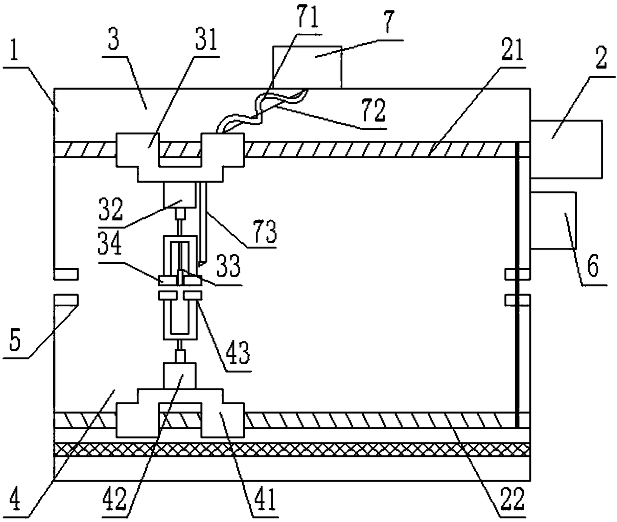
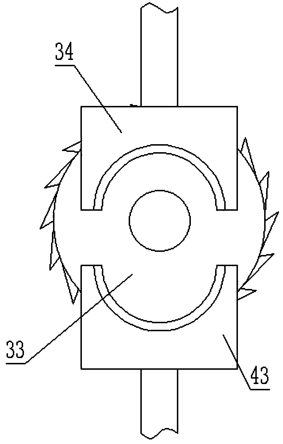
[0019] see Figure 1-2 , a steel bar slitting machine for building construction, comprising a closed casing 1 with a feed port and a discharge port on both sides and a stepping motor 2 positioned on the upper part of the outer wall of the casing 1, and a closed casing 1 is provided with a The driving screw 21 connected to the stepping motor 2 and the driven screw 22 parallel to the driving screw 21 and connected by transmission chain transmission, the driving screw 21 and the driven screw 22 are located on the upper and lower sides of the closed housing 1 respectively. The screw 21 is provided with a fixed cutting module 3 for fixing and cutting the steel bar, and the driven screw 22 is provided with a mobile cutting module 4 for fixing the steel bar; The slitting module 3 and the moving slitting module 4 will fix and cut the steel bars sent into the closed casing 1 by the feed port; the outer wall of the closed casing 1 is provided with a device for setting working parameters...

Embodiment 2

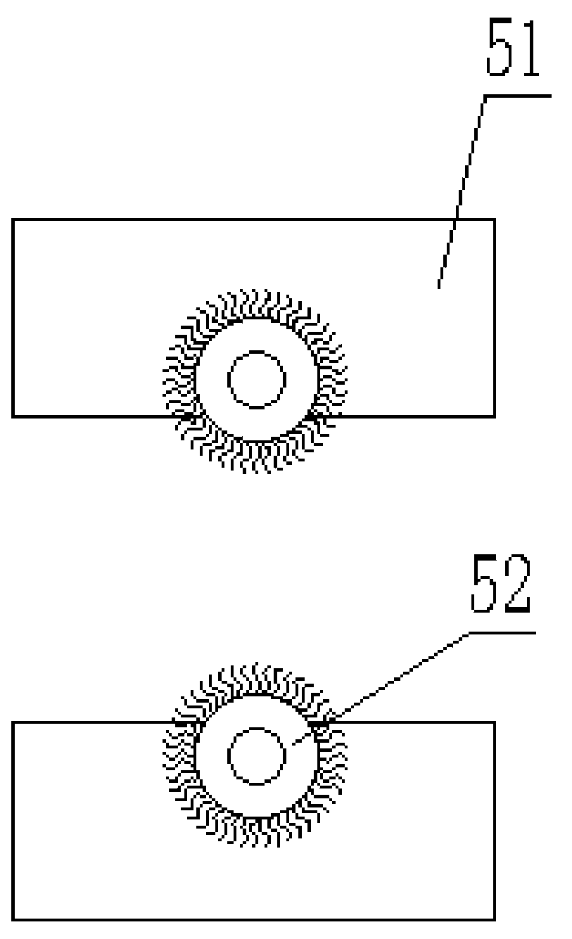
[0027] refer to figure 1 , image 3 , the difference with Embodiment 1 is that, in order to further ensure the working environment in the closed casing 1, and also in order to ensure the efficiency of cutting, a feed dust collector 5 is provided inside the feed port end of the closed casing 1. The dust collector 5 is composed of two fixed pieces 51 located on the upper and lower sides of the feed inlet. A brush 52 driven by a motor to rotate is arranged in the fixed piece 51. When the steel bar enters from the feed port, the brush 52 is started to oppose the surface of the steel bar. Clean up to reduce surface dust.


PUM


Abstract

The invention discloses a reinforcing steel bar slitting machine for building construction. The reinforcing steel bar slitting machine comprises a sealing shell of which the two sides are provided with a feeding port and a discharging port and a stepping motor located at the upper portion of the outer wall of the shell, the sealing shell is internally provided with a driving screw rod which is intransmission connection with the stepping motor and a driven screw rod which is parallel to the driving screw rod and is in transmission connection with the driving screw rod through a transmission chain, the driving screw rod and the driven screw rod are located at the upper and lower sides in the sealing shell respectively, the driving screw rod is provided with a fixing and slitting module usedfor fixing and slitting reinforcing steel bars, and a movable slitting module used for fixing the reinforcing steel bars is arranged on the driven screw rod. According to the reinforcing steel bar slitting machine, the reinforcing steel bars are clamped, fixed and slit through the fixing and slitting module and the movable slitting module, the phenomenon that when conventional slitting equipmentconducts fixing and cutting, the reinforcing steel bars are easily bent is effectively avoided, the reinforcing steel bars can be synchronously conveyed, and the processing efficiency is greatly improved.

Description

technical field [0001] The invention relates to building construction equipment, in particular to a steel bar cutting machine for building construction. Background technique [0002] Rebar is an indispensable material in building construction, and the cutting and processing of rebar is also an essential process on the construction site. In order to ensure the rapid progress of construction, the current construction site has been equipped with rebar cutting machine equipment. [0003] The current steel bar cutting machine is mainly divided into several modules: cutting module, fixing module and conveying module. As the name implies, the cutting module mainly performs cutting work, the fixing module mainly performs the fixing work of the steel bar during cutting, and the conveying module mainly performs the fixing work of the steel bar before and after cutting. Conveying work, and the fixing module of the current steel bar cutting machine is mainly to fix the two ends of the s...

Claims


Application Information

Patent Timeline
Patent Type & Authority Applications(China)
IPC IPC(8): B21F11/00B08B1/02B21F23/00B08B1/20
CPCB21F11/00B21F23/00B08B1/20B08B1/12
Inventor 渠衍飞
Owner 清远市弘亨百建筑有限公司
Learn More