Feeding device used for cold header

A technology of feeding device and cold heading machine, applied in operating device, forging/pressing/hammering device, cleaning method using gas flow, etc. Difficult to move and other problems, to achieve the effect of stable transportation and easy cleaning

Active Publication Date: 2019-01-18
ZHEJIANG QIANGLI FASTENER CO LTD
View PDF6 Cites 6 Cited by
  • Summary
  • Abstract
  • Description
  • Claims
  • Application Information

AI Technical Summary

Problems solved by technology

[0004] There are following defects in the above-mentioned prior art scheme: 1. Although the scraper plate is used to scrape off the metal chips on the surface of the magnet, there is a gap between the magnets, and the metal chips in the gap are difficult to remove; 2. The setting of the discharge plate makes The finished fasteners can fall from the circular conveying line to the discharge plate when they pass by, but the distance between the discharge plate and the magnet is 1 mm to 7 mm, and the metal filings on the surface of the magnet are easily affected by the discharge plate when they pass by. The plate is obstructed and piled up on the front end of the discharge plate, and the scraper arranged under the second rotary end cannot effectively play a role, making it difficult for bolts, nuts and other fasteners to move to the discharge plate; especially nuts, When the nut is laid flat, it cannot roll over like a bolt, and it is more difficult to move to the discharge plate

Method used


Image

  • Feeding device used for cold header
  • Feeding device used for cold header
  • Feeding device used for cold header

Examples


Embodiment Construction

[0036] The present invention will be described in further detail below in conjunction with the accompanying drawings.

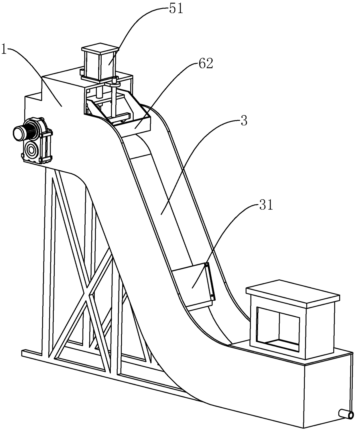
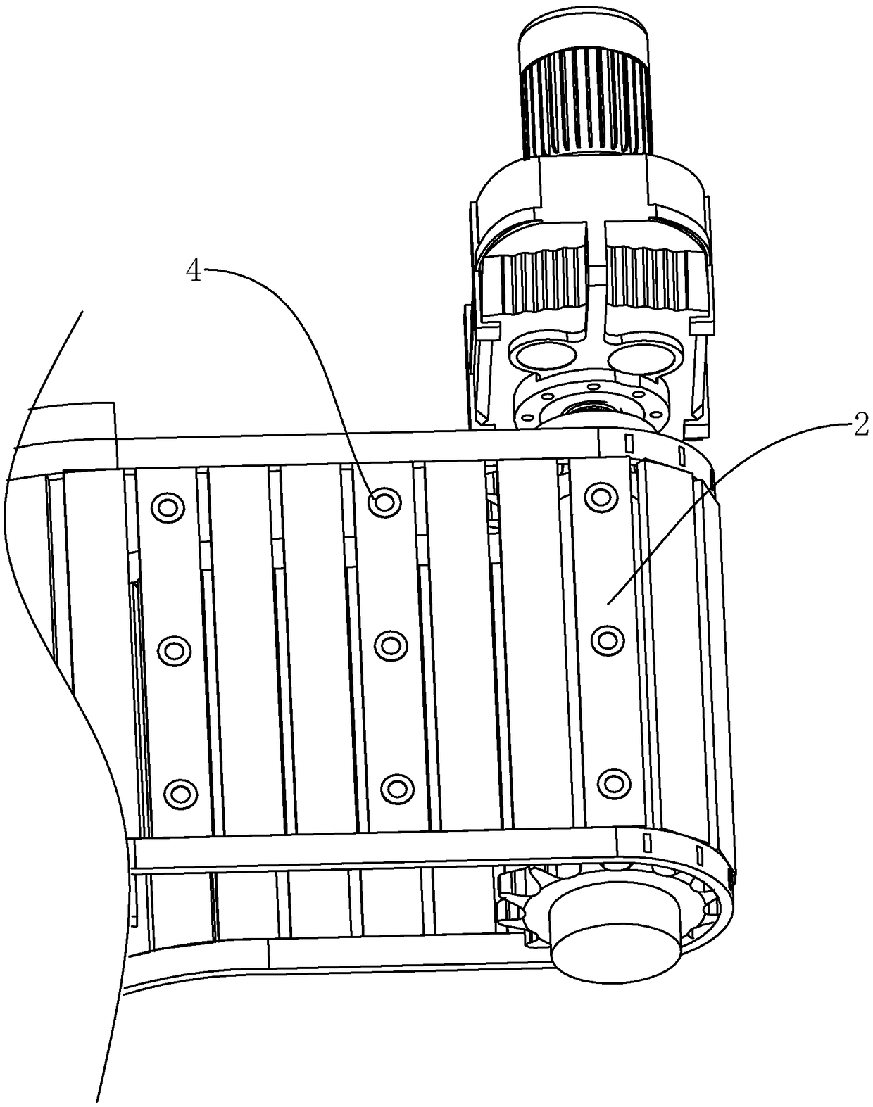
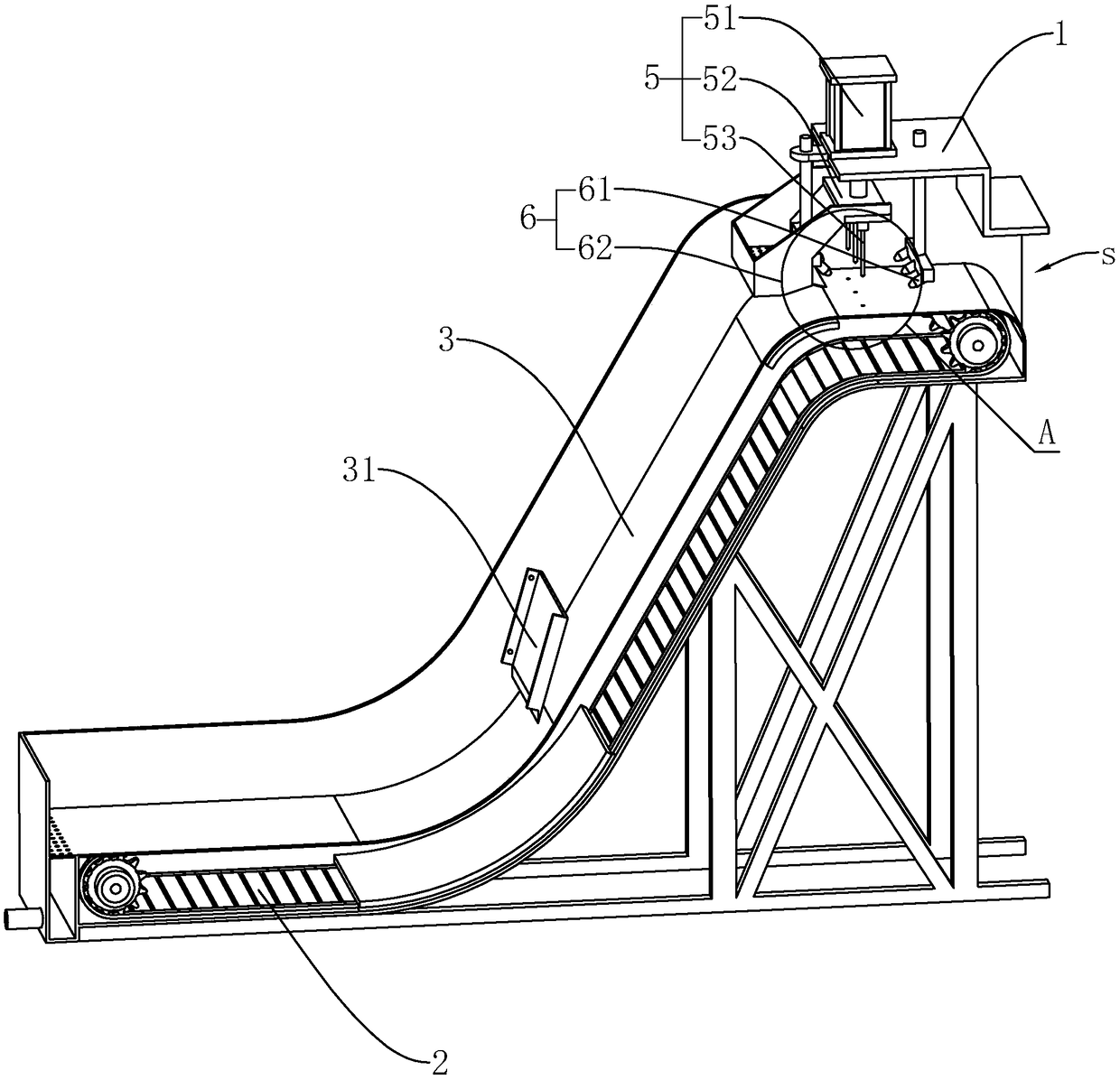
[0037] This embodiment discloses a feeding device for a cold heading machine, such as figure 1 , figure 2 As shown, it includes a frame 1 and a conveying mechanism installed on the frame 1 . The conveying mechanism includes a chain plate conveyor belt 2 driven by a geared motor and a delivery groove 3 fixed above the chain plate conveyor belt 2. A plurality of magnets 4 are fixed side by side on the chain plate of the chain plate conveyor belt 2, and the delivery groove 3 is made of stainless steel, and The bottom of the conveying trough 3 fits with the magnet 4 on the chain plate conveyor belt 2. When the nut falls into the conveying trough 3, it can be attracted by the magnet 4 and bonded to the conveying trough 3; and when the chain plate conveyor belt 2 operates , the nut can also be adsorbed and move relative to the delivery trough 3 .

[0038] Since...


PUM


Abstract

The invention relates to the technical field of cold headers, and aims at providing a feeding device used for a cold header. The device comprises a rack, a conveying belt and a conveying groove; a plurality of magnets are arranged on the conveying belt at intervals; the conveying groove is formed in the upper portion of the conveying belt, and the bottom of the conveying groove fits the magnets onthe conveying belt; a limiting mechanism and a cleaning mechanism are arranged on the parts, above the discharging end, of the rack; the limiting mechanism comprises a downward pressing air cylinderand downward pressing members, and the positions of the downward pressing members correspond to the magnets; the cleaning mechanism comprises a cleaning nozzle connected with an air compressor. According to the feeding device, the conveying belt and conveyed fastening members are separated by using the conveying groove, the fastening members are driven to move by using the absorbing effect of themagnets separated by conveying groove so that metal dust and lubricating oil can completely fall in the conveying groove, the environment is not polluted, the cleaning of the conveying groove is convenient, the interior of the conveying groove has no gap and pit, the metal dust cannot be accumulated, the conveying of the fastening members is not blocked, and therefore the conveying is more stable.

Description

technical field [0001] The invention relates to the technical field of cold heading machines, in particular to a feeding device for cold heading machines. Background technique [0002] The cold heading machine is a special equipment mainly used for mass production of fasteners such as nuts and bolts. After the production of nuts and bolts is completed, the formed products are generally conveyed by conveyor belts. In the prior art, metal residues such as metal scraps are likely to be generated during the production process of fasteners such as nuts and bolts, which will cause products and conveyor belts to be covered with metal scraps. [0003] At present, the Chinese patent document with the authorized announcement number CN206153493U in the prior art discloses a feeding mechanism for cold heading machines, including a frame and an annular conveying line arranged on the frame. The left side of the annular conveying line is the first One rotary end, the right side is the se...

Claims


Application Information

Patent Timeline
Patent Type & Authority Applications(China)
IPC IPC(8): B21K27/00B03C1/16B08B5/02B07B13/00B07B13/16
CPCB03C1/16B07B13/00B07B13/16B08B5/023B21K27/00
Inventor 钱成森
Owner ZHEJIANG QIANGLI FASTENER CO LTD
Why Eureka
Try Eureka