Numerical control lathe for synchronously cleaning away cutting scraps in time

A numerical control lathe and timely technology, applied in the field of numerical control lathes, can solve the problems of waste of coolant, inability to solve the problem of coolant separation work, blockage, etc., and achieve the effect of saving water resources

Active Publication Date: 2019-01-18
JIANGXI TAISHENG INDAL
View PDF6 Cites 17 Cited by
  • Summary
  • Abstract
  • Description
  • Claims
  • Application Information

AI Technical Summary

Problems solved by technology

[0002] When processing mechanical parts, it is necessary to use a CNC lathe. For example, a Chinese patent discloses "a CNC lathe that removes cutting waste synchronously and in time" (Patent No.: CN107398568A), which can remove solid waste and process waste. The processed CNC lathe has the advantages of removing solid waste and treating waste, which prolongs the service life of the CNC lathe and improves the service life of the CNC lathe. However, when the patent processes mechanical parts, if the volume of the waste is large , it is very easy to cause blockage, which affects the follow-up work, and the way of using the water flow to drive the waste to fall to the box is obviously not good. In practice, there will still be waste left on the upper surface of the box. Using the water guide plate Exporting the water body directly will easily cause waste of water resources. Coolant is generally used in the processing of mechanical parts. This patent cannot solve the separation work after mixing the coolant and water, which also causes waste of coolant.

Method used


Image

  • Numerical control lathe for synchronously cleaning away cutting scraps in time
  • Numerical control lathe for synchronously cleaning away cutting scraps in time
  • Numerical control lathe for synchronously cleaning away cutting scraps in time

Examples


Embodiment Construction

[0026] The following will clearly and completely describe the technical solutions in the embodiments of the present invention with reference to the accompanying drawings in the embodiments of the present invention. Obviously, the described embodiments are only some, not all, embodiments of the present invention. Based on the embodiments of the present invention, all other embodiments obtained by persons of ordinary skill in the art without making creative efforts belong to the protection scope of the present invention.

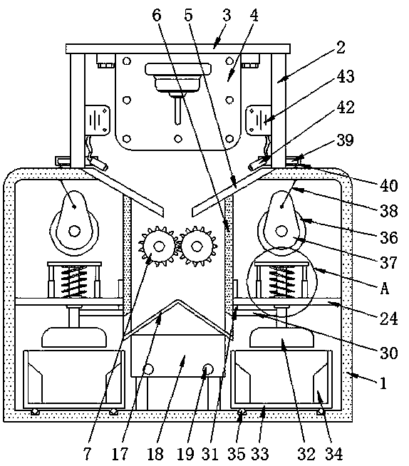
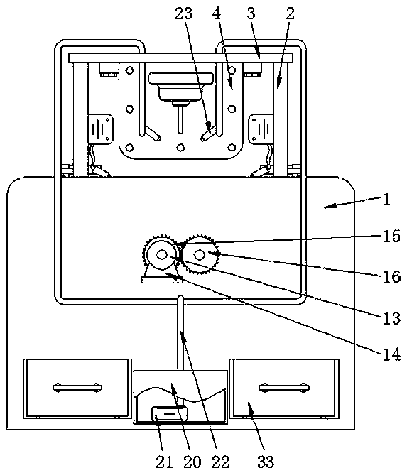
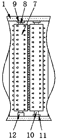
[0027] see Figure 1-6 , the present invention provides a technical solution: a CNC lathe for synchronously removing cutting waste in time, comprising a housing 1, the upper surface of the housing 1 is fixedly connected with the lower surfaces of two side plates 2, and the two sides The upper surface of the plate 2 is fixedly connected with the lower surface of the top plate 3, and the lower surface of the top plate 3 is fixedly connected with the organic body...


PUM


Abstract

The invention discloses a numerical control lathe for synchronously cleaning away cutting scraps in time. The lathe comprises a shell. The upper surface of the shell is fixedly connected with the lower surfaces of two side plates. The upper surfaces of the two side plates are fixedly connected with the lower surface of a top plate. The lower surface of the top plate is fixedly connected with a machine body through a bolt. A motor a is started by an external power supply, an output shaft of the motor a rotates and drives two smashing rollers to rotate oppositely through a coupler, a rotating shaft a, a gear a, a gear b and a rotating shaft b, when the scraps pass through a material guide plate and enter the shell, the scraps are smashed under the effect of the smashing rollers, the blockagecaused by scrap accumulation is prevented, an air compressor pumps in air to compress the air, the compressed air is then sprayed out of an air nozzle through a telescopic hose, and therefore the scraps are blown off the material guide plate through air spraying instead of water flushing, water resources are saved, and there is not need to separate a water body and a coolant.

Description

technical field [0001] The invention belongs to the technical field of numerical control machining, and in particular relates to a numerical control lathe which can synchronously and timely remove cutting waste. Background technique [0002] When processing mechanical parts, it is necessary to use a CNC lathe. For example, a Chinese patent discloses "a CNC lathe that removes cutting waste synchronously and in time" (Patent No.: CN107398568A), which can remove solid waste and process waste. The processed CNC lathe has the advantages of removing solid waste and treating waste, which prolongs the service life of the CNC lathe and improves the service life of the CNC lathe. However, when the patent processes mechanical parts, if the volume of the waste is large , it is very easy to cause blockage, which affects the follow-up work, and the way of using the water flow to drive the waste to fall to the box is obviously not good. In practice, there will still be waste left on the up...

Claims


Application Information

Patent Timeline
Patent Type & Authority Applications(China)
IPC IPC(8): B23B25/00B23Q11/00
CPCB23B25/00B23Q11/00B23Q11/0042B23Q11/005
Inventor 候领华
Owner JIANGXI TAISHENG INDAL
Why Eureka
Try Eureka