Punching device for bearing production

A punching device and bearing production technology, applied in the direction of boring/drilling, drilling/drilling equipment, maintenance and safety accessories, etc., can solve the problem that dust is easy to accumulate on the work surface, affecting the quality and efficiency of drilling, Easily damaged bearings and other problems, to achieve the effect of improving drilling efficiency, reasonable structural design, and ensuring drilling quality

Inactive Publication Date: 2019-01-18
钟国强
View PDF4 Cites 3 Cited by
  • Summary
  • Abstract
  • Description
  • Claims
  • Application Information

AI Technical Summary

Problems solved by technology

Theoretically speaking, it is impossible to achieve the function of transmission. Not only that, but the bearing will also affect the transmission. In order to reduce this influence, good lubrication must be achieved on the bearing of the high-speed shaft. Some bearings themselves have been lubricated, called pre-lubricated bearings, and Most of the bearings must have lubricating oil. When running at high speed, the friction will not only increase the energy consumption, but what is more terrible is that it is easy to damage the bearings.
[0003] During production, it is usually necessary to drill holes for bearing raw materials. The existing punching devices can only punch holes for one workpiece at a time, which is inefficient. At the same time, the dust generated during punching is easy to accumulate on the work surface, requiring frequent cleaning. , affecting the punching quality and efficiency

Method used


Image

  • Punching device for bearing production
  • Punching device for bearing production
  • Punching device for bearing production

Examples


Embodiment Construction

[0022] The following will clearly and completely describe the technical solutions in the embodiments of the present invention with reference to the accompanying drawings in the embodiments of the present invention. Obviously, the described embodiments are only some, not all, embodiments of the present invention. Based on the embodiments of the present invention, all other embodiments obtained by persons of ordinary skill in the art without making creative efforts belong to the protection scope of the present invention.

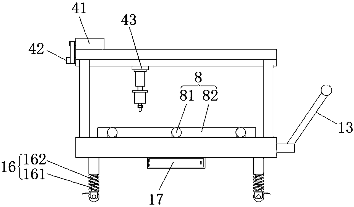
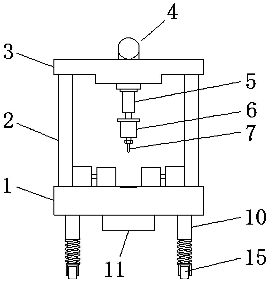
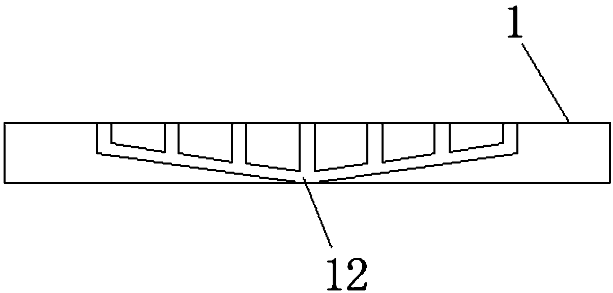
[0023] see Figure 1-4 , the present invention provides a technical solution: a punching device for bearing production, including a base 1, a support rod 2 is arranged on the upper surface of the base 1, and a horizontal plate 3 is fixedly installed on the top of the support rod 2, The horizontal plate 3 is a hollow structure, the horizontal plate 3 is provided with a sliding mechanism 4, the sliding mechanism 4 is provided with a first hydraulic cylinder 5, a...


PUM


Abstract

The invention discloses a punching device for bearing production. The device comprises a base, supporting rods are arranged on the upper surface of the base, and a horizontal plate is fixedly installed at the tops of the supporting rods; a sliding mechanism is arranged on the horizontal plate, a first hydraulic cylinder is arranged on the sliding mechanism, and a motor is fixedly installed on a piston rod of the first hydraulic cylinder through a fixing base; a drill bit is fixedly installed on an output shaft of the motor through a shaft sleeve, a clamping mechanism is arranged on the upper surface of the base, and a clamping groove is formed in a clamping block; supporting legs are fixedly installed on the lower surface of the base, a dust collection box is fixedly installed on the lowersurface of the base, and a chute is formed in the base and communicated with the dust collection box. According to the punching device for bearing production, multiple bearings to be punched can be simultaneously punched, the punching efficiency is improved, dust generated during punching can be collected, convenience is provided for cleaning, and meanwhile the dust can be prevented from accumulating on the upper surface of the base.

Description

technical field [0001] The invention relates to the technical field of bearing production, in particular to a punching device for bearing production. Background technique [0002] Bearings are an important part of contemporary mechanical equipment. Its main function is to support the mechanical rotating body, reduce the friction coefficient during its movement, and ensure its rotation accuracy. In terms of its function, it should be a support, that is, it is used to support the shaft literally, but this is only part of its function. The essence of support is to be able to bear radial loads. It can also be understood that it is used to fix the shaft. Bearing quick and easy automatic selection is included. It is to fix the shaft so that it can only achieve rotation, while controlling its axial and radial movement. A motor won't work at all without bearings. Because the shaft may move in any direction, and the motor is required to only rotate when it is working. Theoretic...

Claims


Application Information

Patent Timeline
Patent Type & Authority Applications(China)
IPC IPC(8): B23B41/00B23Q11/00
CPCB23B41/00B23Q11/0032B23Q11/0042
Inventor 钟国强
Owner 钟国强
Why Eureka
Try Eureka