Intelligent clamp and control method thereof

A fixture and intelligent technology, applied in the field of intelligent fixture and its control, can solve the problems of large working space, poor dust removal effect, affecting equipment performance and production environment, etc., and achieve good effect of dust removal and waste removal

Pending Publication Date: 2019-01-18
江苏维力安智能科技有限公司
View PDF11 Cites 4 Cited by
  • Summary
  • Abstract
  • Description
  • Claims
  • Application Information

AI Technical Summary

Problems solved by technology

[0002] In the field of laser processing technology, especially laser cutting equipment, smoke and dust are usually generated during the cutting process, which affects equipment performance and production environment. Solving the problem of smoke and dust generated by laser cutting is a common problem in this field. At present, the dust removal system is mainly used to clean the entire The workbench is used for dust removal work, because the work space is large, the dust removal effect is not good

Method used


Image

  • Intelligent clamp and control method thereof
  • Intelligent clamp and control method thereof
  • Intelligent clamp and control method thereof

Examples


Embodiment 1

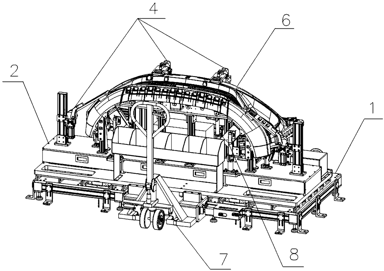
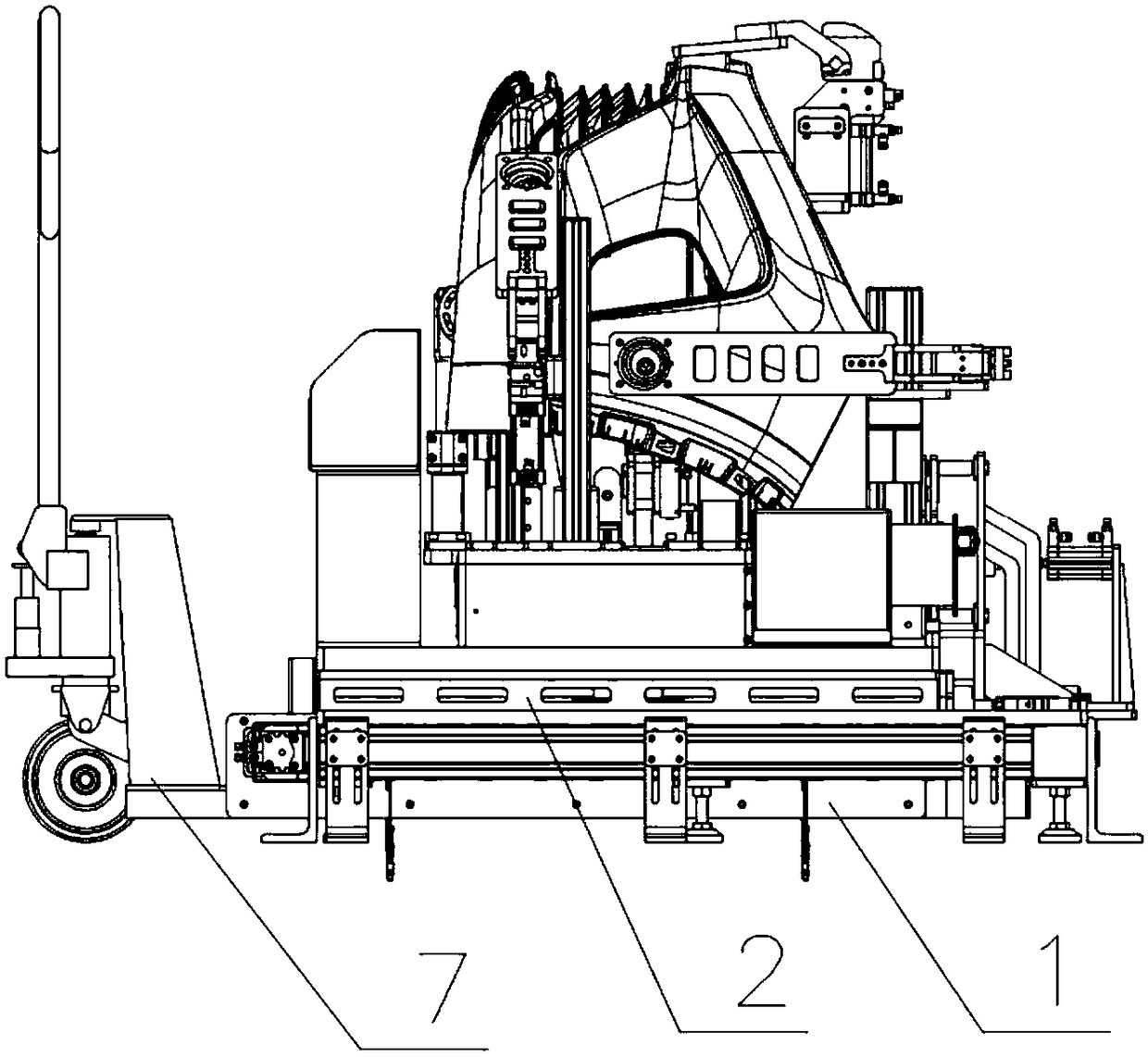
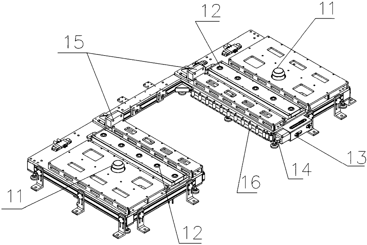
[0056] 1) The fixture body is in place: first call the corresponding fixture body 2 according to the number of the workpiece 6, manually use the special forklift 7 to transport the fixture body 2 to the base 1, and the special forklift 7 enters the position between the two rectangular bases, When the front side of the clamp body 2 touches the anti-collision block 15 on the base 1, the special forklift 7 stops moving forward. During this period, the positioning mechanism 13 on one side of the base 1 cooperates with the positioning groove 71 on the special forklift to complete the locked positioning of the special forklift 7, and thus completes the initial positioning between the clamp body 2 and the base 1; then the central control system Control the rise of the universal ball 12 on the base 1, stop rising when the apex of the universal ball 12 touches the bottom of the fixture body 2, then manually control the special forklift 7 to descend, and the weight of the fixture body 2 ...

Embodiment 2

[0062] Application example of the intelligent fixture of the present invention in the radar hole cutting and radar bracket installation process of the automobile bumper: in the prior art, the radar hole cutting and the radar bracket installation on the automobile bumper are usually completed by two processes successively , in the embodiment of the smart fixture of the present invention, only a simple improvement to the fixture body 2 is needed to combine the cutting of the radar hole and the installation of the radar bracket into one process, which can improve work efficiency. The improvement scheme is as follows: the above-mentioned improvement can be completed by adding a radar support push assembly on the existing fixture body 2. The radar support push assembly 8 is composed of a support seat 81, a sensor 82, a push mechanism 83 and a radar support column 84. The radar support pushes Component 8 is fixedly installed on the upper surface of waste material collection chamber 2...


PUM


Abstract

The invention discloses an intelligent clamp and a control method thereof. The intelligent clamp comprises a clamp body (2) installed on a base (1), the clamp body (2) is provided with a supporting device (3) and a pressing device (4), and comprises a waste material collecting cavity (21) and a clamp control cabinet (23), the waste material collecting cavity (21) is provided with a smoke discharging assembly (5) which comprises a smoke discharging pipeline (51) and a lifting mechanism (52), the lower end of the smoke discharging pipeline (51) is inserted into an inner cavity of the waste material collecting cavity (21), the top end of the smoke discharging pipeline (51) can get close to a through hole (411) in the front end of a pressing plate (41) of the pressing device (4), and the through hole (411) corresponds to a cutting hole in position; the clamp control cabinet (23) is connected with the lifting mechanism (52) and an opening and closing mechanism (42) in the pressing device (4) through cables. With the intelligent clamp, in-place detection, clamping and place taking of the smoke discharging pipeline can be automatically realized for workpieces.

Description

technical field [0001] The invention relates to the technical field of laser processing, in particular to an intelligent fixture used in conjunction with laser processing equipment and a control method thereof. Background technique [0002] In the field of laser processing technology, especially laser cutting equipment, smoke and dust are usually generated during the cutting process, which affects equipment performance and production environment. Solving the problem of smoke and dust generated by laser cutting is a common problem in this field. At present, the dust removal system is mainly used to clean the entire The workbench is used for dust removal work, because the work space is large, and the dust removal effect is not good. Contents of the invention [0003] The purpose of the present invention is to solve the problems existing in the prior art, and provide an intelligent fixture used in conjunction with laser processing equipment and its control method; the fixture...

Claims


Application Information

Patent Timeline
Patent Type & Authority Applications(China)
IPC IPC(8): B23K26/70B23K26/16B23K37/04B23K26/38
CPCB23K26/16B23K26/38B23K26/702B23K37/0443
Inventor 赵德强成鸣章敏吴靖李志祥
Owner 江苏维力安智能科技有限公司
Why Eureka
Try Eureka