Positioning mechanism for machining pipes

A technology of positioning mechanism and pipe materials, which is applied in the direction of manufacturing tools, workpiece clamping devices, etc., can solve the problems of time-consuming and labor-intensive, and achieve the effects of high control precision, low cost and simple structure

Inactive Publication Date: 2019-01-18
LUZHOU YUANCHENG ENG MACHINERY CO LTD
View PDF7 Cites 5 Cited by
  • Summary
  • Abstract
  • Description
  • Claims
  • Application Information

AI Technical Summary

Problems solved by technology

However, the above methods are time-consuming and labor-intensive. It has always been a di

Method used


Image

  • Positioning mechanism for machining pipes
  • Positioning mechanism for machining pipes

Examples


Embodiment 1

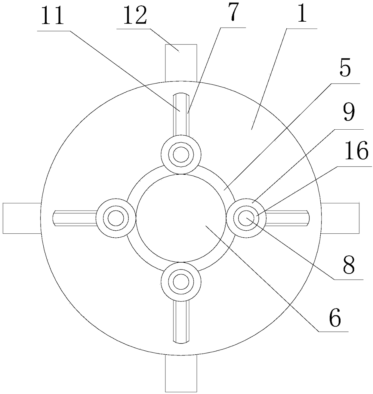
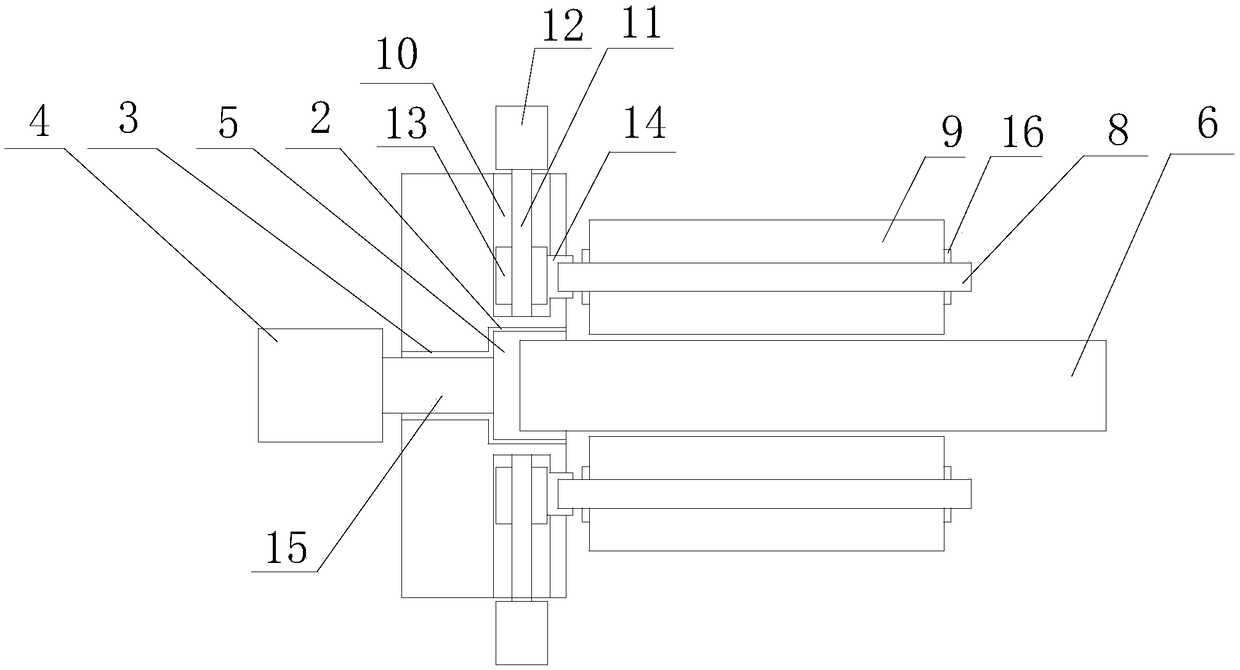
[0025] The invention provides a positioning mechanism for processing pipes, which includes a base 1 with a circular plate structure, a circular hole positioning groove 2 is opened on one side of the base 1, and a positioning groove 2 is opened on the base 1. There is a through hole 3 communicating with the positioning groove 2, and the axis lines of the through hole 3 and the positioning groove 2 coincide; the clamping device also includes a motor 4, and the output shaft 15 of the motor 4 passes through the through hole 3 and is installed The shell 5 is detachably connected, and the installation shell 5 is accommodated in the positioning groove 2; the axial end of the pipe 6 to be processed is detachably fixed on the installation shell 5; the base 1 is provided with a positioning groove 2 There are several slide grooves 7 arranged on the board surface, and the several slide grooves 7 are radially distributed at equal intervals with the positioning groove 2 as the base point, an...

Embodiment 2

[0027] Further improvement on the basis of Embodiment 1, the drive mechanism adopts a screw drive mechanism; a number of mounting holes 10 are opened on the side wall of the base 1, and the mounting holes 10 are evenly closed at equal intervals along the circumference of the base 1 , the axis line of the mounting hole 10 and the axis line of the positioning groove 2 are perpendicular to each other; the mounting hole 10 is provided with a screw 11, and the axial end of the screw 11 extends into the mounting hole 10 and is fixed by a bearing. The axial other end of 11 stretches out mounting hole 10 and is connected with the output end of driving motor 12; Screw mandrel 11 is provided with nut pair 13, and slide block 14 is fixed on the side wall of nut pair 13; Connected, and the radial width of the chute 7 is smaller than the inner diameter of the mounting hole 10, the free end of the slider 14 protrudes from the chute 7, and the axial end of the limiting shaft 8 is fixed on the...

Embodiment 3

[0029]Further improvement on the basis of Embodiment 2, the inner wall of the roller 9 and the outer wall of the limiting shaft 8 are in sliding contact with balls, and one axial end of the limiting shaft 8 is detachably fixed on the plate surface of the base 1 . The axial two ends of described position-limiting shaft 7 are provided with position-limiting collar 16, and the outer diameter of described space-limiting collar 16 is larger than the inner diameter of roller 8, and is smaller than the outer diameter of roller 8, and space-limiting collar 16 passes through The screw is fixed on the limit shaft 7.


PUM


Abstract

The invention discloses a positioning mechanism for machining pipes. A circular-hole positioning groove is formed in the plate face of one side of a circular-plate base, and a through hole communicated with the positioning groove is also formed in the base; an output shaft of a motor runs through the through holes to be detachably connected with an installing shell sleeve, and the installing shellsleeve is contained in the positioning groove; one axial end of a to-be-machined pipe is detachably fixed on the installing shell sleeve; multiple sliding grooves are formed in the plate face of thepositioning groove formed in the base, and are radially distributed with the positioning groove as a base point at equal intervals, one ends of limiting shafts in the axial direction extend into the sliding grooves, the limiting shafts are driven by a driving mechanism to slidingly move in the extending directions of the sliding grooves, rollers sleeve the limiting shafts, the inner walls of the rollers are in rolling connection with the outer walls of the limiting shafts, and the outer walls of the rollers are in frictional contact with the outer wall of the to-be-machined pipe. According tothe positioning mechanism for the machining pipes, it can be avoided that the to-be-machined pipe conducts radial run-out in the rotating process.

Description

technical field [0001] The invention relates to the technical field of mechanical processing, in particular to a positioning mechanism for processing pipes. Background technique [0002] The clamping device is a commonly used device in various mechanical processing processes. It is used to fix the materials or parts to be processed to ensure that they will not move and deviate during the processing, and to avoid the deviation of the items to be processed from affecting the operation. For cylindrical pipes, it is easy to roll during production, processing and cutting, and it is necessary to fix them before subsequent work. The existing pipe fixing devices usually use chains or pipe wrench for fixing, but when the pipe needs to be stretched or a large force is applied, it is easy to cause the phenomenon of pipe detachment, displacement, etc., and the pipe cannot be fixed stably and reliably, and the pipe Jumping will occur during the rotation, which will affect the cutting, g...

Claims


Application Information

Patent Timeline
IPC IPC(8): B25B11/00
CPCB25B11/00
Inventor 马赟
Owner LUZHOU YUANCHENG ENG MACHINERY CO LTD
Why Eureka
Try Eureka