Mounting method and dismounting method of positioning pin

An installation method and positioning pin technology, applied in the field of positioning parts, can solve the problems of time-consuming and laborious, accidents, difficult operation of positioning pins, etc., and achieve the effect of accurate positioning and simple operation.

Active Publication Date: 2019-01-18
TZ COAL MINE MACHINERY
View PDF7 Cites 2 Cited by
  • Summary
  • Abstract
  • Description
  • Claims
  • Application Information

AI Technical Summary

Problems solved by technology

Since the connection between the positioning pin and the pin hole is relatively tight when the interference fit or transition fit is adopted, the conventional installation and removal method of the positioning pin is to use manpower to knock the positioning pin or the workpiece to realize the alignment of the positioning pin. At this time, the disassembly and assembly of the positioning pin has the problems of difficult operation, time-consuming and laborious; and when disassembling the positioning pin, due to the deviation of the knocking point, there may be unbalanced force on the workpiece and the positioning pin and Locating pins come out and other problems, resulting in damage to the mating surface of the locating pin and the workpiece and personal safety accidents

Method used


Image

  • Mounting method and dismounting method of positioning pin
  • Mounting method and dismounting method of positioning pin

Examples


Embodiment Construction

[0028] In order to make the purpose, technical solution and advantages of the present invention clearer, the technical solution of the present invention will be clearly and completely described below in conjunction with specific embodiments of the present invention and corresponding drawings. Apparently, the described embodiments are only some of the embodiments of the present invention, but not all of them. Based on the embodiments of the present invention, all other embodiments obtained by persons of ordinary skill in the art without making creative efforts fall within the protection scope of the present invention.

[0029] The technical solutions provided by the embodiments of the present invention will be described in detail below in conjunction with the accompanying drawings.

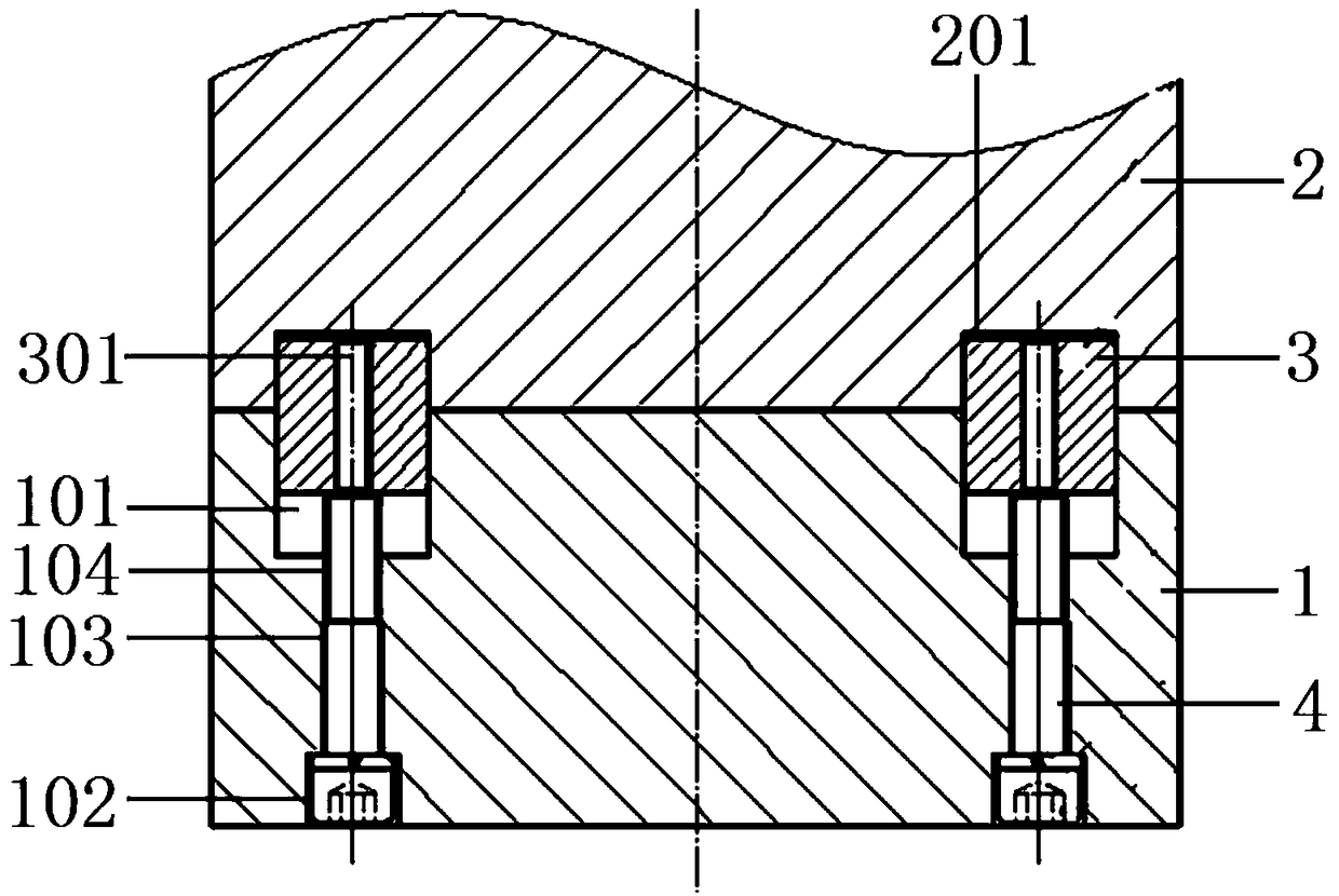
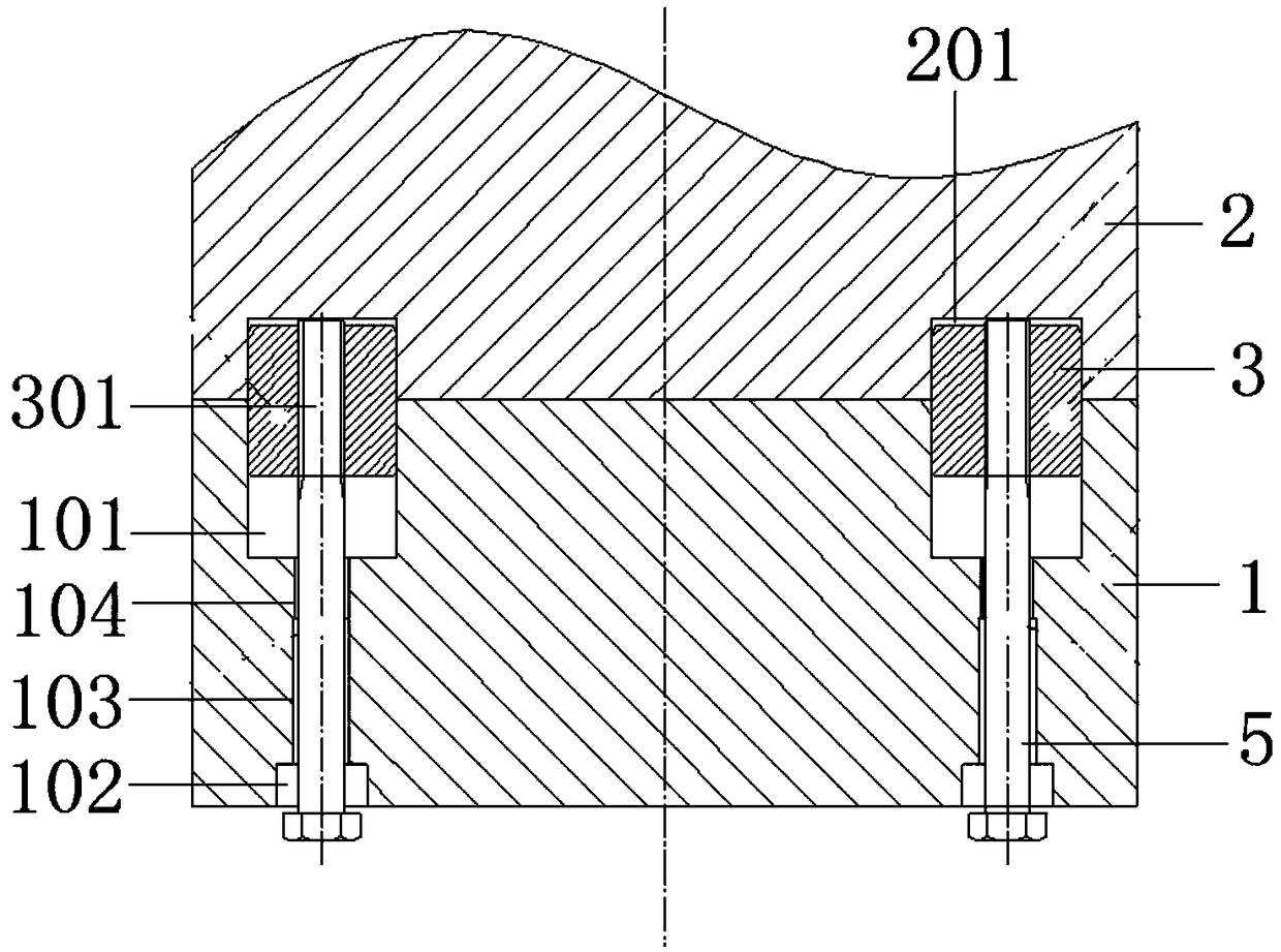
[0030] As shown in the drawings, the embodiment of the present invention provides a positioning pin installation method, the installation method is used to install the positioning pin 3 in the firs...


PUM


Abstract

The invention discloses a mounting method and a dismounting method of a positioning pin. The mounting method and the dismounting method are used for mounting and dismounting the positioning pin between a first part and a second part. The installation method comprises the following steps: 11) processing a first positioning pin hole; 12) processing a first counterbore, a second counterbore and a first threaded through hole; 13) processing a second threaded through hole and a chamfer; 14) processing a second positioning pin hole; 15) placing a positioning pin; 16) screwing a first bolt; and 17) turning the first bolt and jacking the positioning pin. The disassembling method comprises the following steps: 21) screwing out the first bolt; 22) screwing a second bolt; 23) turning the second boltand jacking the second part. The mounting method and the dismounting method of the positioning pin can quickly mount and dismount the positioning pin between the first part and the second part, achieve the matching positioning and separation of the first part and the second part, solve the problem that the positioning pin and the part are easy to be damaged in the dismounting process. The mountingmethod and the dismounting method of the positioning pin have the advantages of simple operation, safety, reliability and accurate positioning.

Description

technical field [0001] The invention relates to the technical field of positioning parts, in particular to a method for installing and disassembling a positioning pin. Background technique [0002] At present, commonly used locating parts include locating pins, which can quickly realize the mutual positioning of two workpieces by using locating pins. The mutual cooperation of the pin holes realizes the coordinated positioning of the two workpieces. Among them, in order to ensure the positioning effect, improve the bearing capacity and connection strength, the positioning pin and the pin hole are connected and matched by interference fit or transition fit. Since the connection between the positioning pin and the pin hole is relatively tight when the interference fit or transition fit is adopted, the conventional installation and removal method of the positioning pin is to use manpower to knock the positioning pin or the workpiece to realize the alignment of the positioning p...

Claims


Application Information

Patent Timeline
Patent Type & Authority Applications(China)
IPC IPC(8): B25B27/00
CPCB25B27/00
Inventor 庞俊峰庞晓丽熊世伟刘泽平武仕源黄丽琴周翔李瑞锋赵灵闫鹏飞刘涛李维伟
Owner TZ COAL MINE MACHINERY
Why Eureka
Try Eureka