Parallel type all-in-one machine for robot joints
A robot joint and integrated machine technology, which is applied to manipulators, program-controlled manipulators, manufacturing tools, etc., can solve the problems that the axial length of the servo reducer integrated machine cannot be further reduced, and the overall axial length of the overall mechanism can be reduced, so as to achieve a flat structure. , Simple installation, reasonable design effect
- Summary
- Abstract
- Description
- Claims
- Application Information
AI Technical Summary
Problems solved by technology
Method used
Image
Examples
Embodiment 1
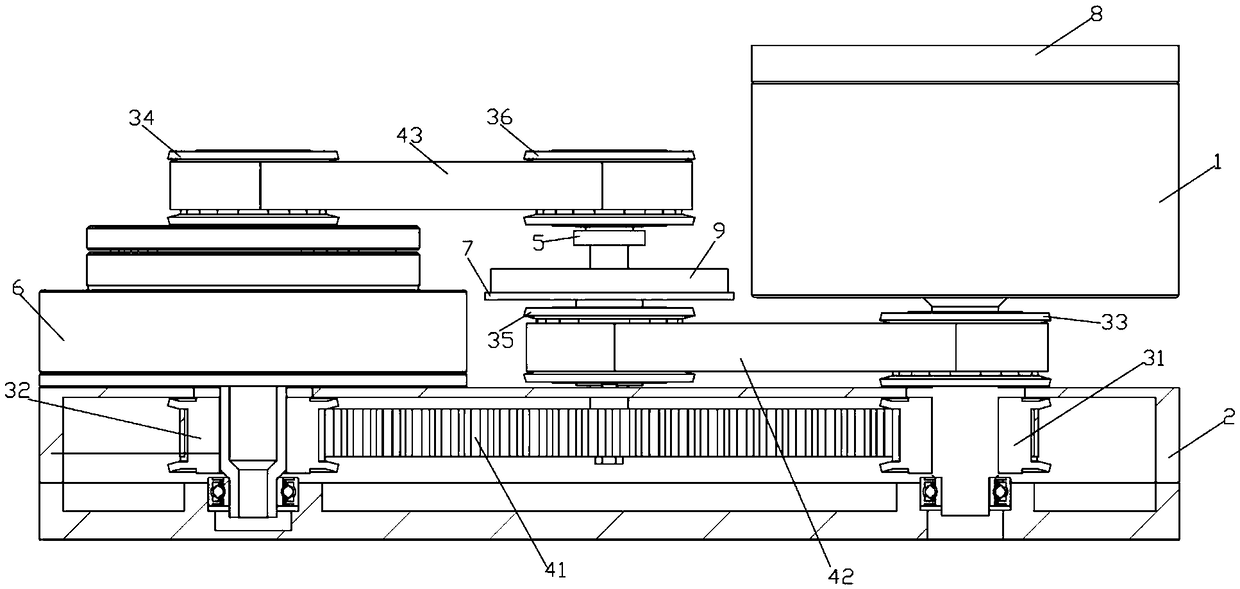
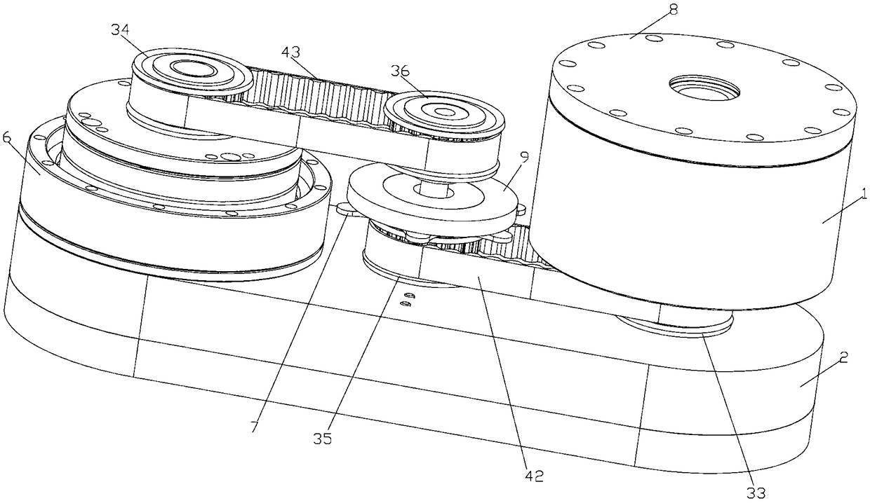
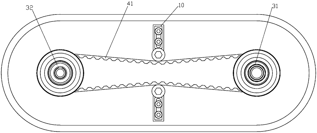
[0040] Such as Figure 1-3 As shown, the present invention provides an all-in-one machine for parallel robot joints, which consists of a servo motor 1, a connecting base 2, a synchronous pulley, a synchronous belt, a low-speed shaft encoder 5, a harmonic reducer 6, and a brake Mechanism 7, servo drive module 8, high-speed shaft encoder 9, tensioning mechanism 10 and so on.
[0041] The connection base 2 is a hollow structure; the servo motor 1 is fixed on the first end of the connection base 2, the motor shaft of the servo motor 1 extends into the connection base 2, and a The first synchronous pulley 31.
[0042] The reducer 6 is fixed on the second end of the connecting base 2, the high-speed shaft of the reducer 6 extends into the connecting base 2, and a second synchronous pulley 32 is arranged on the extending end of the high-speed shaft; The first synchronous pulley 31 and the second synchronous pulley 32 are linked through a first synchronous belt 41 , so that the serv...
Embodiment 2
[0052] Such as Figure 4-6 As shown, the servo motor 1 is connected to the bottom plate of the connection base 2 through screws, the first synchronous pulley 31 is connected to the motor shaft through a top screw or a key, the upper end of the motor shaft is fixed to the upper cover of the connection base 2 through a bearing, and the harmonic deceleration The device 6 is also connected to the bottom plate of the connection base 2 through screws, the high-speed hollow shaft of the harmonic reducer 6 is connected to the second synchronous pulley 32 through a top screw, and the first synchronous pulley 31 at the motor end is connected to the high-speed shaft of the harmonic reducer 6 The second synchronous pulley 32 is connected through the first synchronous belt 41, and the tensioning mechanism 10 on both sides can tension the first synchronous belt 41 in the middle, and the low-speed shaft encoder 5 and the reducer 6 low-speed shaft 61 pass the jackscrew or interference The low...
Embodiment 3
[0056] Such as Figure 7 As shown, the inner wall of the connection base 2 is rotatably installed with a second shaft body 21 parallel to and spaced from the motor shaft, and a second shaft body 21 is rotatably arranged on the second shaft body 21 and is distributed parallel to the first synchronous pulley 31. The seventh synchronous pulley 37, the seventh synchronous pulley 37 is arranged in parallel with the first synchronous belt 41 at intervals, and the first synchronous pulley 31 and the seventh synchronous pulley 37 are linked by a fourth synchronous belt 44 The second shaft body 21 protrudes outward from the connection base 2 for a certain distance, and the high-speed shaft encoder 9 is arranged on the connection base 2 on the outer periphery of the protruding end of the second shaft body 21 , so that the input shaft of the high-speed shaft encoder 9 rotates synchronously with the protruding end of the second shaft body 21 for collecting the rotational position of the m...
PUM
 Abstract
Description
Claims
Application Information
 - R&D
- Intellectual Property
- Life Sciences
- Materials
- Tech Scout
- Unparalleled Data Quality
- Higher Quality Content
- 60% Fewer Hallucinations
Browse by: Latest US Patents, China's latest patents, Technical Efficacy Thesaurus, Application Domain, Technology Topic, Popular Technical Reports.
© 2025 PatSnap. All rights reserved.Legal|Privacy policy|Modern Slavery Act Transparency Statement|Sitemap|About US| Contact US: help@patsnap.com


