Cement homogenizing equipment with automatic charging function
A technology of automatic feeding and homogenizing equipment, which is applied in the direction of cement mixing device, unloading device, clay preparation device, etc. It can solve the problems of screening structure, single mixing function, large space occupation, high energy consumption of equipment, etc., and achieve power connection The method is ingenious and reasonable, the design is ingenious and reasonable, and the effect of preventing accumulation and clogging
- Summary
- Abstract
- Description
- Claims
- Application Information
AI Technical Summary
Problems solved by technology
Method used
Image
Examples
Embodiment 1
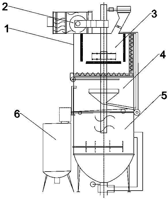
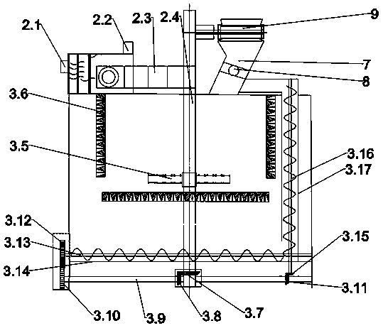
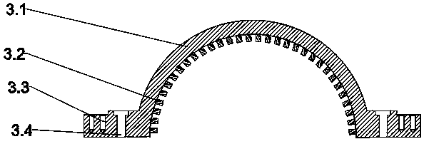
[0033] As shown in the accompanying drawings of the description, a cement homogenization equipment with automatic feeding function includes equipment tank 1, driving mechanism 2, breaking bin 3, screening bin 4, mixing bin 5, auxiliary mechanism 6 and feeding Mechanism 9; the driving mechanism 2 is fixed on the top of the equipment tank 1 and driven by a water turbine. The two ends of the driving mechanism 2 are connected with a water inlet 2.1 and a water outlet 2.2, and the output of the driving mechanism 2 is connected to a gearbox 2.3 , the output of the gearbox 2.3 is connected to the main shaft 2.4; the main shaft 2.4 is fixed at the middle position of the equipment tank 1, and passes through the breaking bin 3, the screening bin 4 and the mixing bin 5; the breaking bin 3 is equipped with a breaking cutter head 3.5, a counterattack plate 3.6, a horizontal screw conveyor 3.13 and a vertical screw conveyor 3.16. The breaking cutter head 3.5 is fixed on the installation posi...
Embodiment 2
[0041] The structure and principle of the present embodiment 2 are basically the same as that of the embodiment 1, except that the sieve hole 3.61 is provided with a spiked partition 3.63 between the two holes, the bottom of the spiked partition 3.63 is supported, and the spikes on the head are connected to the bottom of the spiked partition. The upper sieve surface is parallel, and the material is thrown out by the centrifugal force of the breaking cutter, and then collides with the sharp part of the head of the sharp partition 3.63, so that the material can be effectively broken.
Embodiment 3
[0043] The structure and principle of this embodiment 3 are basically the same as that of embodiment 1, except that three groups of material level detection sensors 5.4 are arranged on the tank wall of the mixing discharge bin 5, and the material level detection sensors 5.4 are installed in the mixing discharge bin 5. On the upper, middle, and bottom tank walls, the feedback signal of the material level detection sensor 5.4 is connected to the control system, and the control system automatically controls the opening and closing of the switch valve 8 on the feed inlet 7 according to the change of the feedback signal, and controls the feed amount .
PUM
 Abstract
Description
Claims
Application Information
 - R&D
- Intellectual Property
- Life Sciences
- Materials
- Tech Scout
- Unparalleled Data Quality
- Higher Quality Content
- 60% Fewer Hallucinations
Browse by: Latest US Patents, China's latest patents, Technical Efficacy Thesaurus, Application Domain, Technology Topic, Popular Technical Reports.
© 2025 PatSnap. All rights reserved.Legal|Privacy policy|Modern Slavery Act Transparency Statement|Sitemap|About US| Contact US: help@patsnap.com


