Method for improving lateral printing accuracy and printer thereof
A technology of printing accuracy and printer, which is applied in printing and other fields, can solve problems such as difficulty in wide application, increase in quantity, and restriction of printing accuracy, and achieve the effect of simple and effective method, simple structure, and favorable market promotion
- Summary
- Abstract
- Description
- Claims
- Application Information
AI Technical Summary
Problems solved by technology
Method used
Image

Examples
Embodiment 1
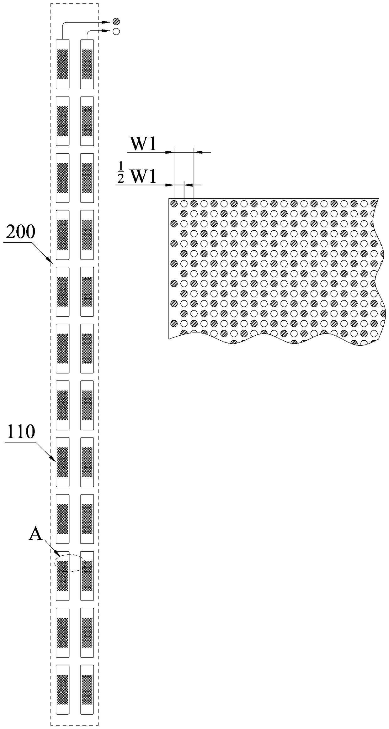
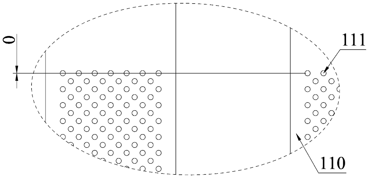
[0029] A method for improving the accuracy of horizontal printing, using two rows of nozzles 110 arranged side by side along the lateral direction of the printer to print the same ink, and making the printing starting points between the two rows of nozzles 110 staggered by 1 / 2 of the first unit W1 , the first unit W1 is the center-to-center distance between two adjacent nozzle holes 111 of the nozzle head 110 in the lateral direction of the printer. In this embodiment, two rows of nozzles 110 arranged side by side along the lateral direction of the printer are used to print the same ink. The printing starting points between the two rows of nozzles 110 are staggered by 1 / 2 of the first unit W1, and the printing accuracy can be increased to twice the original. The method is simple and effective, and there is no need to improve the original nozzles 110 or replace them. The cost is not only the higher precision nozzle 110 which is twice the cost of the original nozzle 110, it is eco...
Embodiment 2
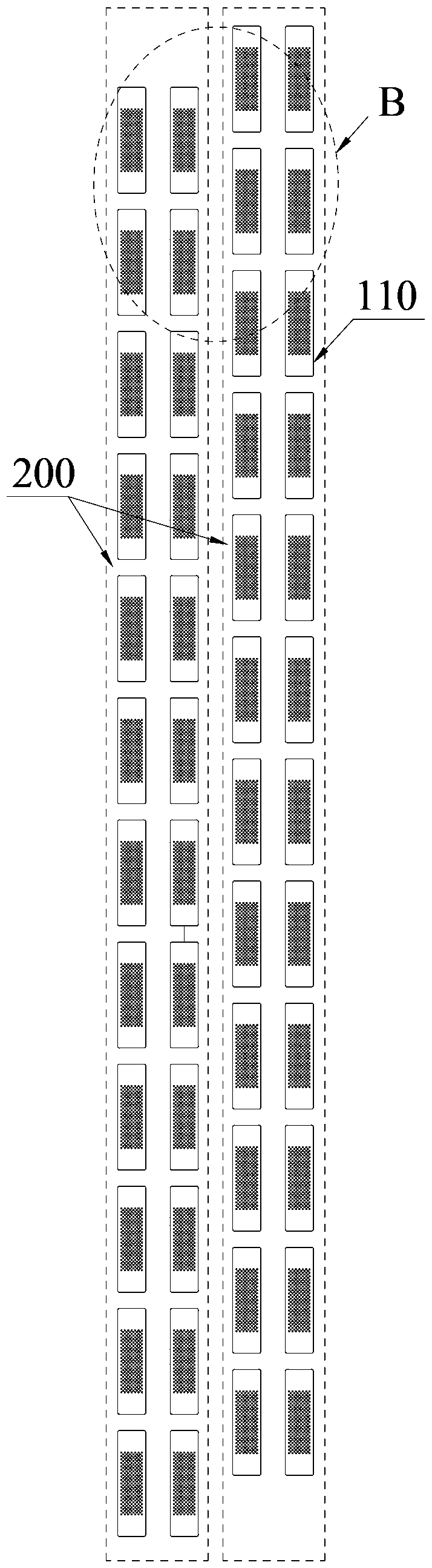
[0032] As an improvement to the above-mentioned method embodiment, in this embodiment, two printing units 200 arranged in the lateral direction of the printer are used to print the same ink, and the two printing units 200 are staggered by 1 / 2 in the longitudinal direction of the printer. A second unit W2, the second unit W2 is the center distance between two adjacent nozzles 110 in any row of nozzles 110 in the longitudinal direction of the printer. Each of the printing units 200 includes two rows of nozzles 110 arranged in the transverse direction of the printer, and the two rows of nozzles 110 are staggered by 1 / 2 of the first unit W1 in the longitudinal direction of the printer. The first unit W1 is the center distance between two adjacent nozzle holes 111 of the nozzle 110 in the longitudinal direction of the printer.
[0033] The nozzle 110 is a high-precision component, which means that its price is relatively expensive. As we all know, in industrial printing, the format...
Embodiment 3
[0036] As an improvement to the above-mentioned method embodiment, this embodiment uses two rows of nozzles 110 or two printing units 200 of the same printing module on the printer to print the same ink, that is, two rows of nozzles 110 that print the same ink or two rows of nozzles that print the same ink The printing unit 200 is uniformly arranged on the same printing module, which can better and more easily ensure the positional accuracy between the nozzles 110 and 110 and between the printing unit 200 and the printing unit 200, reduce assembly difficulty, and improve assembly efficiency.
[0037] Device Example 1
[0038] A printer applying the above-mentioned method for improving lateral printing accuracy, comprising a conveying platform for conveying printing media and a printing system located above the conveying platform, said printing system comprising several printing units 200 arranged along the lateral direction of the printer, said The printing unit 200 includes t...
PUM
 Abstract
Description
Claims
Application Information
 - Generate Ideas
- Intellectual Property
- Life Sciences
- Materials
- Tech Scout
- Unparalleled Data Quality
- Higher Quality Content
- 60% Fewer Hallucinations
Browse by: Latest US Patents, China's latest patents, Technical Efficacy Thesaurus, Application Domain, Technology Topic, Popular Technical Reports.
© 2025 PatSnap. All rights reserved.Legal|Privacy policy|Modern Slavery Act Transparency Statement|Sitemap|About US| Contact US: help@patsnap.com