A production line conveying equipment with hydraulic top pendulum for manual processing

A technology for conveying equipment and production lines, which is applied to conveyor objects, transportation and packaging, etc., can solve the problems of serious cervical spine and spine injuries, easy to cause occupational diseases, and increase work load, etc., to reduce hand load and less manual control. Demand, avoid blocking effects

Active Publication Date: 2020-06-26
山东鹤鹏技术有限公司
View PDF5 Cites 0 Cited by
  • Summary
  • Abstract
  • Description
  • Claims
  • Application Information

AI Technical Summary

Problems solved by technology

[0006] In view of the deficiencies in the prior art, the purpose of the present invention is to provide a production line conveying equipment with a hydraulic top swing that is convenient for manual processing, so as to solve the problem that the production line conveying equipment in the prior art is in a continuous working state, and the staff must remove the processed parts from the conveyor belt. The processing can only be carried out on the processing table. Because the processing table is located between the staff and the conveyor belt, the staff needs to stand up and lean over to pick and place the processed parts, which is inconvenient. The traditional manual processing method is to place the processed parts with the conveyor belt. On the processing table, the staff bends down and lowers their heads to process, which will cause great damage to the cervical spine and spine of the staff, and may easily cause occupational diseases; manual control is used to pick and place the processed parts, which increases the workload of the hands.

Method used


Image

  • A production line conveying equipment with hydraulic top pendulum for manual processing
  • A production line conveying equipment with hydraulic top pendulum for manual processing
  • A production line conveying equipment with hydraulic top pendulum for manual processing

Examples


Embodiment Construction

[0027] In order to make the technical means, creative features, goals and effects achieved by the present invention easy to understand, the present invention will be further described below in conjunction with specific embodiments.

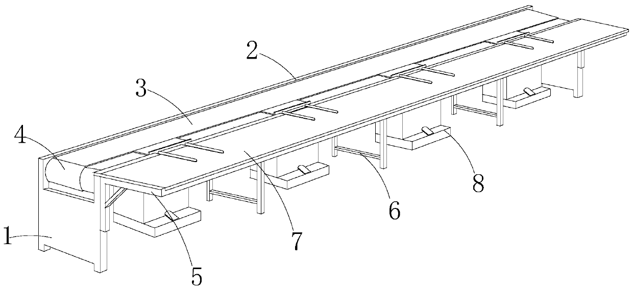
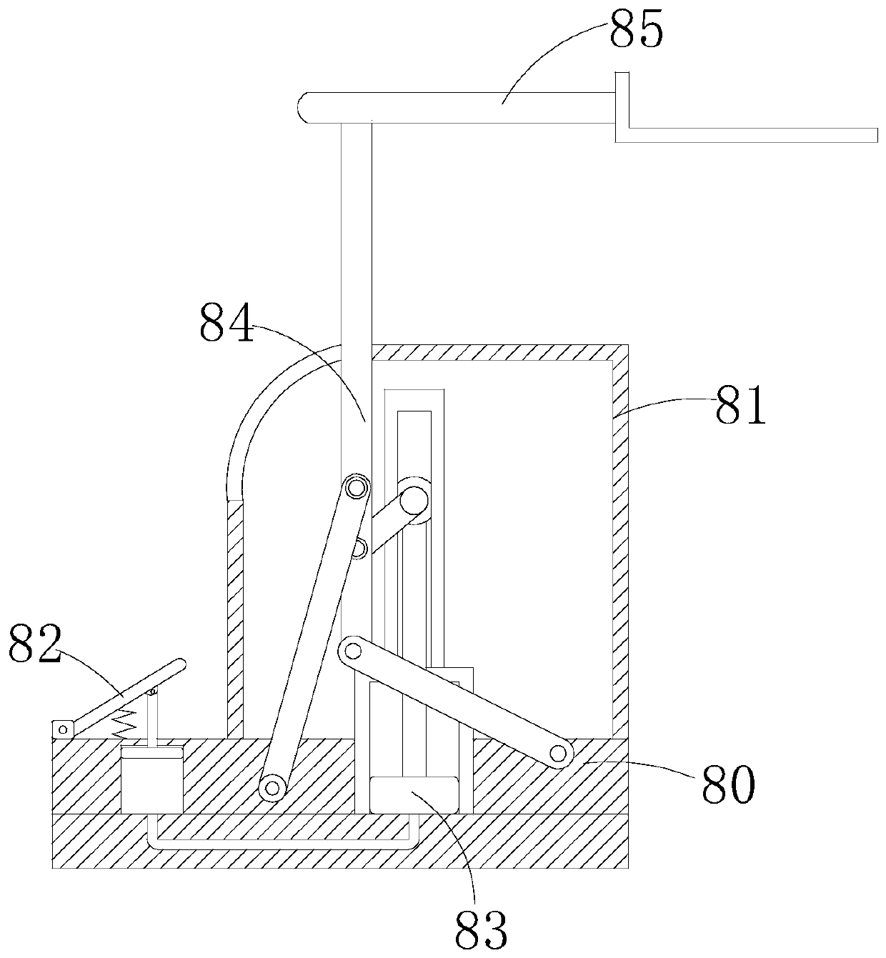
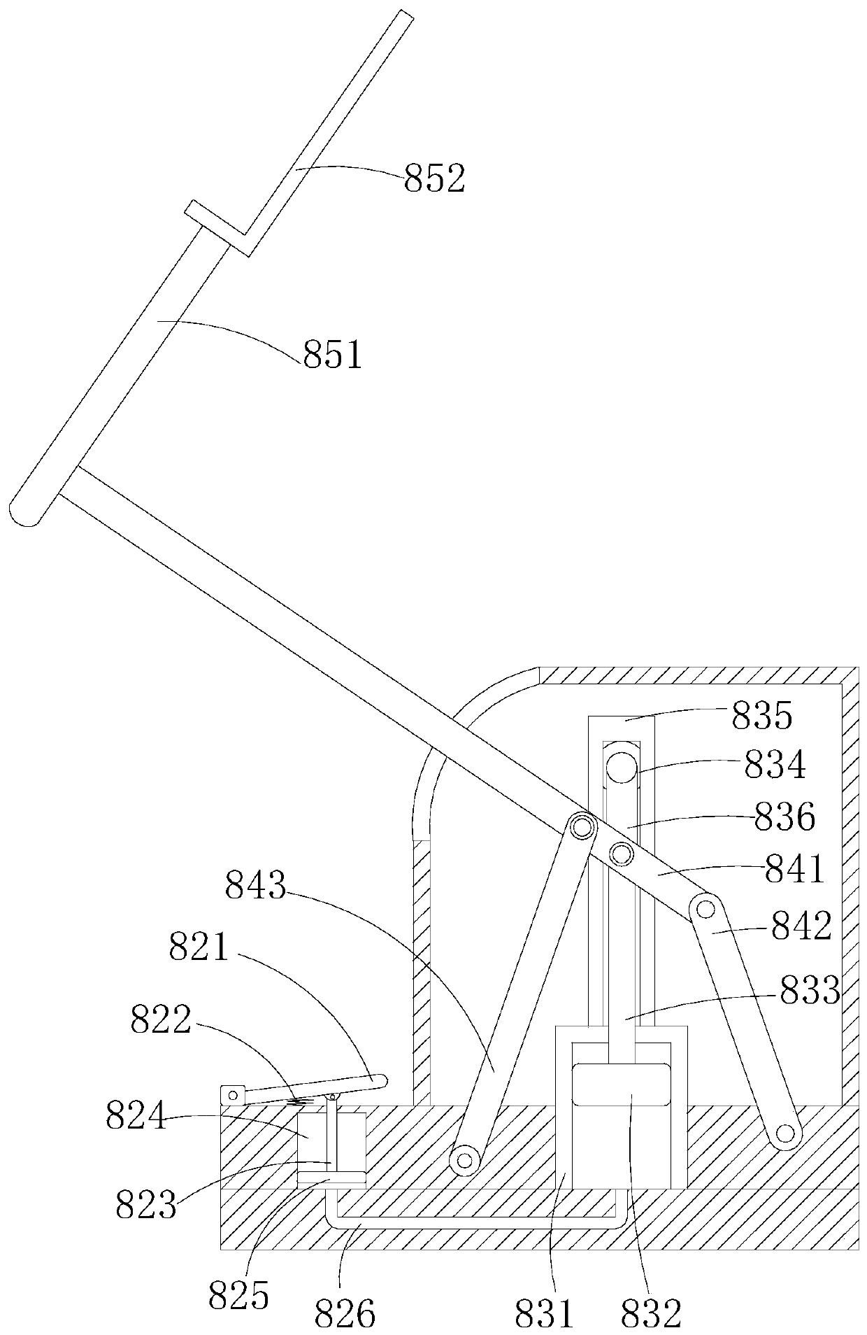
[0028] Such as Figure 1-Figure 3 As shown, the present invention provides a technical scheme of a production line conveying equipment with a hydraulic top swing that is convenient for manual processing:

[0029] A production line conveying equipment with a hydraulic top pendulum that is convenient for manual processing. Auxiliary device 8, the support cabinet 1 is provided with two, the side baffle 2 is arranged on the upper part between the two support cabinets 1 and connected by electric welding, the conveyor belt 3 is arranged between the side baffles 2 and The two ends are engaged and movably connected with the driving roller 4, the triangular bracket 5 is arranged on the upper front of the supporting cabinet 1 and is fixedly connected by el...


PUM


Abstract

The invention discloses a hydraulic top swing production line conveying device beneficial for manual machining. The conveying device structurally comprises a supporting cabinet, side baffles, a conveying belt, a driving roller, a triangular support, a supporting foot tripod, a machining table and a hydraulic top swing machining auxiliary device. Through an L-type table plate, under the cooperationeffect of conveying belts at different heights on the front side and the rear side, to-be-machined pieces are taken out of the conveying belts to be machined or put back onto the conveying belts after being machined, the to-be-machined pieces are taken and put easily and conveniently on the premise of not influencing the normal conveying, and workers do not need to stand up or bow; through a topswing mechanism, the to-be-machined pieces can be driven to swing forwards and upwards, the workers can effectively protect the cervical vertebras and spines without bowing or lowering the heads during machining, and meanwhile it can be avoided that machining light is shielded by bowing and head lowering; through a stepping hydraulic mechanism, the to-be-machined pieces can be easily controlled tobe taken and put through stepping, hand control requirements are reduced, and hand burdens are relieved.

Description

technical field [0001] The invention relates to the field of conveying equipment, more precisely, it is a production line conveying equipment with a hydraulic top swing that facilitates manual processing. Background technique [0002] At present, the production line basically adopts the production line method. With the development of science and technology, most of them have been mechanized, but some processes still require manual processing. However, the conveying equipment required in this production line has the following defects: [0003] 1. The conveying equipment is in a continuous working state. The staff must take the processed parts from the conveyor belt to the processing table before processing. Because the processing table is located between the staff and the conveyor belt, the staff needs to stand up to pick and place the processed parts It is more inconvenient to lean forward; [0004] 2. The traditional manual processing method is to place the workpiece on th...

Claims


Application Information

Patent Timeline
Patent Type & Authority Patents(China)
IPC IPC(8): B65G47/74B65G47/04
CPCB65G47/04B65G47/74
Inventor 欧植英
Owner 山东鹤鹏技术有限公司
Why Eureka
Try Eureka