Railway high embankment vertical diaphragm box structure

A box-shaped structure and high-fill technology, applied in the directions of roads, buildings, tracks, etc., can solve problems such as unreported, and achieve the effects of simple construction technology, land saving and poor adaptability

Pending Publication Date: 2019-01-18
CHINA RAILWAY ERYUAN ENG GRP CO LTD
View PDF8 Cites 0 Cited by
  • Summary
  • Abstract
  • Description
  • Claims
  • Application Information

AI Technical Summary

Problems solved by technology

However, there is no report on the research and applicati

Method used


Image

  • Railway high embankment vertical diaphragm box structure
  • Railway high embankment vertical diaphragm box structure

Examples


Embodiment Construction

[0018] The present invention will be further described below in conjunction with the accompanying drawings and embodiments.

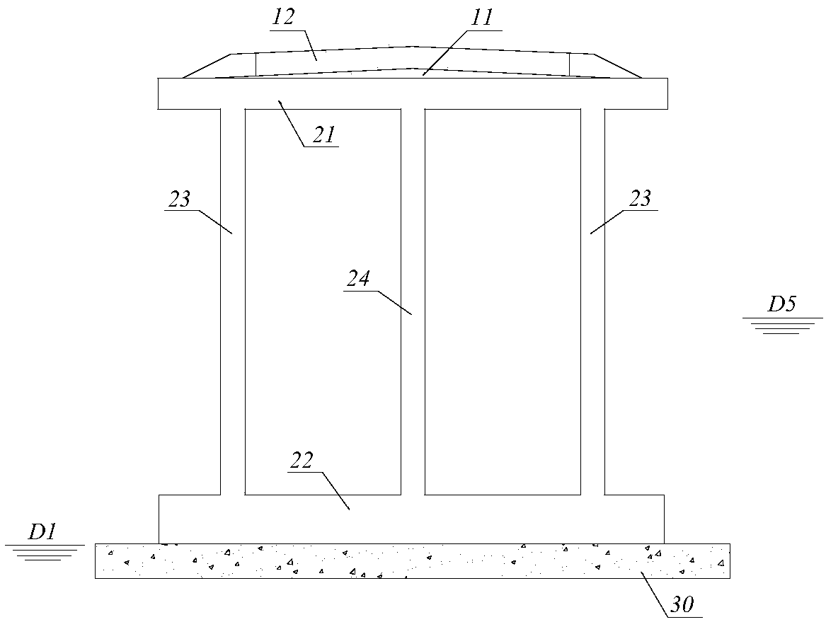
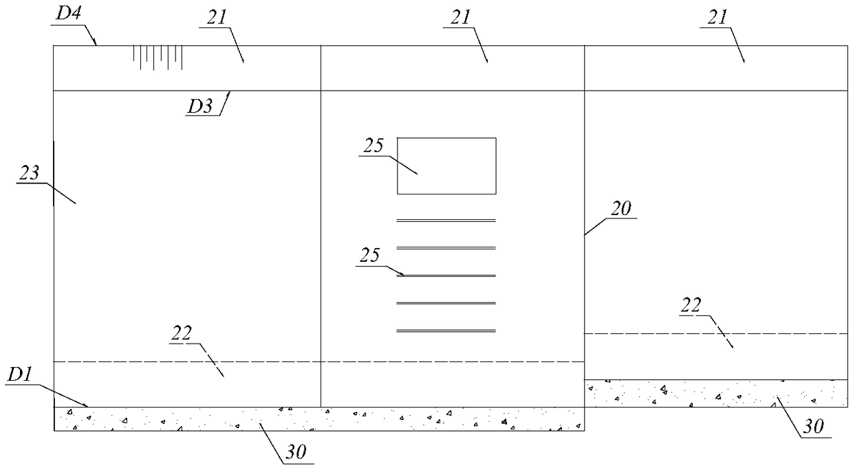
[0019] refer to figure 1 , the present invention railway high-fill embankment vertical partition type box structure comprises the reinforced concrete box section section that is arranged continuously along the embankment extension direction, and each reinforced concrete box section section is made up of top plate 21, bottom plate 22, web on both sides 23 and the vertical middle partition 24 between the webs 23 on both sides are integrally poured. The lateral ends of the top plate 21 and the bottom plate 22 respectively extend out from the webs 23 on the same side to form an overhang structure, and the bottom plate 22 is located on the sand cushion 30 . The bottom layer 11 of the foundation bed and the surface layer 12 of the foundation bed are sequentially constructed on the top plate 21 from bottom to top.

[0020] refer to figure 1 , Compared with ...


PUM


Abstract

In order to effectively improve the overall rigidity of the box structure and reduce the stress on the web, the invention provides a railway high embankment vertical diaphragm box structure to meet the safety and stability requirements of the railway high embankment slope and to solve the durability problem of the embankment structure. Comprises continuously arranged reinforced concrete box-shapedsegments along the extension direction of the embankment, wherein each reinforced concrete box-shaped segment is integrally poured by a top plate, a bottom plate, two side webs and a vertical middlepartition plate located between the two side webs; the upper end of the reinforced concrete box-shaped segment is arranged, and the lower end is respectively consolidated with the top plate and the bottom plate into a vertical middle partition plate; The top plate and the transverse two ends of the bottom plate respectively extend out the same side web plate to form an outer overhanging structure,and the bottom plate is seated on the sand cushion layer; A base bed bottom layer and a base bed surface layer are sequentially constructed on the top plate from bottom to top.

Description

technical field [0001] The invention relates to a railway embankment structure, in particular to a novel high-fill embankment structure aimed at areas with strict restrictions on land use and lack of stone materials. Background technique [0002] With the vigorous development of my country's railway construction, the requirements for economy and adaptability are getting higher and higher in the construction process. Especially in places where the topography is limited and the properties of the structure are limited, such as the conditions where the slope of the high fill embankment at the bridge head is limited. In the above situation, if the scheme of extending the bridge section or adopting the gravity (balanced weight) retaining wall to close the slope will inevitably increase the large investment, and the gravity (balanced weight) retaining wall has higher requirements on the bearing capacity of the foundation. Therefore, in order to reduce investment, meet the applicab...

Claims


Application Information

Patent Timeline
IPC IPC(8): E01B2/00
CPCE01B2/00E01B2/006
Inventor 蒋楚生肖世国邹川黄晶李庆海司文明贺钢易旭鹏曾惜齐远李飞黄献璋许颖兰小平
Owner CHINA RAILWAY ERYUAN ENG GRP CO LTD
Why Eureka
Try Eureka