Multi-stage green assembling cantilever-type reinforced earth retaining wall

A cantilever type, reinforced soil technology, applied in construction, artificial island, infrastructure engineering, etc., can solve the problems of large bending moment and shear force of the wall body, large horizontal displacement of the wall top, cumbersome construction process, etc. The effect of bending moment and shear force, reducing horizontal displacement, and improving slope stability

Pending Publication Date: 2019-01-18
CHINA RAILWAY ERYUAN ENG GRP CO LTD
View PDF5 Cites 5 Cited by
  • Summary
  • Abstract
  • Description
  • Claims
  • Application Information

AI Technical Summary

Problems solved by technology

[0004] The traditional cantilever retaining wall has the following disadvantages: the height of the wall should not exceed 6m, and it is difficult to be suitable for higher filling works; the horizontal displacement of the top of the wall is relatively large, which is not good for the deformation control of the subgrade under long-term operation; The body bears a large bending moment and shear force; it can only be cast-in-place, and the construction process is relatively cumbersome; it is difficult to achieve the overall greening effect of the supported roadbed slope
The two-stage stacked cantilever retaining wall has no platform between the two-stage walls, which is not conducive to the overall stability of the slope, and is not convenient for vegetation slope protection.
The stepped reinforced soil retaining wall has the advantages of light weight and earthquake resistance, but the overall structure resistance to deformation is relatively weak

Method used


Image

  • Multi-stage green assembling cantilever-type reinforced earth retaining wall
  • Multi-stage green assembling cantilever-type reinforced earth retaining wall
  • Multi-stage green assembling cantilever-type reinforced earth retaining wall

Examples


Embodiment Construction

[0021] The present invention will be further described below in conjunction with the accompanying drawings and embodiments.

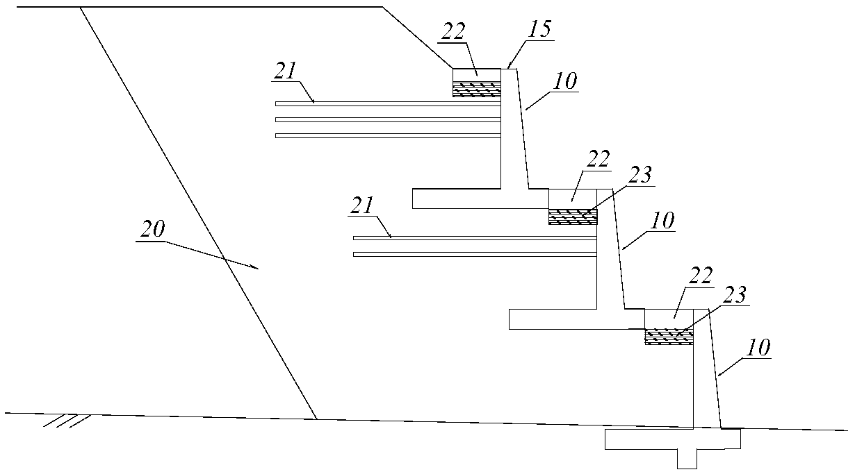
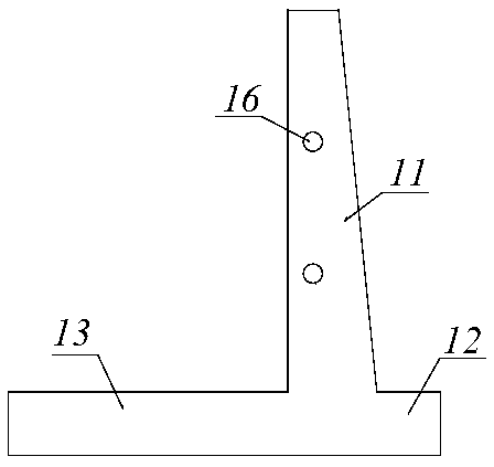
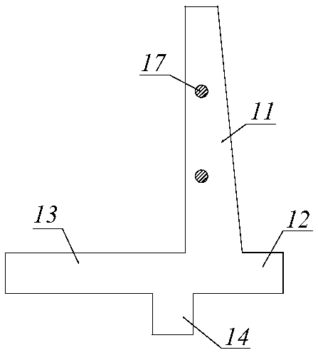
[0022] refer to figure 1 , the multi-stage green assembled cantilever reinforced soil retaining wall of the present invention, the cantilever reinforced soil retaining wall is arranged step-by-step on the filling soil body 20, and the cantilever reinforced soil retaining wall at all levels is composed of reinforced concrete cantilever type The retaining wall segments 10 are spliced ​​horizontally, between the top of the next cantilever reinforced earth retaining wall and the bottom of the previous group of cantilever reinforced earth retaining walls, the uppermost cantilever reinforced earth retaining wall A step 22 is formed between the top of the top and the slope of the filling soil body 20, and green plants are planted in the step 22 to form a green belt 25. Two adjacent reinforced concrete cantilever retaining wall segments 10 of the same level ca...


PUM


Abstract

A multi-stage green assembling cantilever-type reinforced earth retaining wall is suitable for higher filling engineering to effectively reduce horizontal displacement of the top of the wall and favorable for limiting the deformation of the roadbed to improve the stability of the side slope, and can achieve the environmental protection effect of covering low wall back and greening slope through the vegetation slope protection. A cantilever-type reinforced earth retaining wall is arranged on a filling square soil body according to a stepped classification, the cantilever-type reinforced earth retaining wall at all levels is transversely spliced by a reinforced concrete cantilever-type retaining wall segment, a step is formed between the top of the next-stage cantilever-type reinforced earthretaining wall and the bottom of the upper set of cantilever-type reinforced earth retaining wall, and between the top of the uppermost forming stage cantilever-type reinforced earth retaining wall and the slope surface of the filling square soil body, and green plants are planted in the step to form a green belt; two adjacent segments of reinforced concrete cantilever-type retaining wall of thesame level of cantilever-type reinforced earth retaining wall are connected with each other by a splicing structure; a geogrid type pull rib is arranged in the filling square soil body in a layered mode, and the outer end of each geogrid type pull rib is fixedly connected with the vertical arm of the corresponding cantilever reinforced earth retaining wall.

Description

technical field [0001] The invention relates to a cantilever retaining wall, in particular to a multi-stage assembled cantilever reinforced earth retaining wall with relatively high filling soil, which can advantageously control the deformation of the roadbed and stabilize the side slope. Background technique [0002] With the rapid development of national economic construction, there will be more and more mountainous railway and highway projects. High-fill subgrades are very common in road construction in mountainous areas. Cantilever retaining walls (L-shaped retaining walls) are commonly used retaining structures when land use restrictions are strict or foundation bearing capacity is low. [0003] The current code stipulates that the height of traditional cantilever retaining walls should not be greater than 6m. At the same time, under the action of filling pressure and vehicle load, the horizontal displacement of the top of the wall is generally large, especially under ...

Claims


Application Information

Patent Timeline
Patent Type & Authority Applications(China)
IPC IPC(8): E02D29/02
CPCE02D29/0241
Inventor 蒋楚生肖世国贺钢李庆海司文明齐远李昭颖邹川许颖曾惜
Owner CHINA RAILWAY ERYUAN ENG GRP CO LTD
Why Eureka
Try Eureka