Adjustment mechanism for blades of axial flow fan and fan

A technology of blade adjustment and axial flow fan, which is applied in the direction of machine/engine, mechanical equipment, pump control, etc., can solve the problem of poor stability of blade angle adjustment, and achieve the effect of simple structure and strong stability

Pending Publication Date: 2019-01-18
CHENGDU TECHCAL UNIV
View PDF8 Cites 5 Cited by
  • Summary
  • Abstract
  • Description
  • Claims
  • Application Information

AI Technical Summary

Problems solved by technology

[0004] The purpose of the present invention is to provide an axial flow fan blade adjustment mechanism and fan, ai

Method used


Image

  • Adjustment mechanism for blades of axial flow fan and fan
  • Adjustment mechanism for blades of axial flow fan and fan
  • Adjustment mechanism for blades of axial flow fan and fan

Examples


Embodiment

[0039] This embodiment provides a fan, which includes an axial flow fan blade adjustment mechanism 1 , and its specific structure is described below.

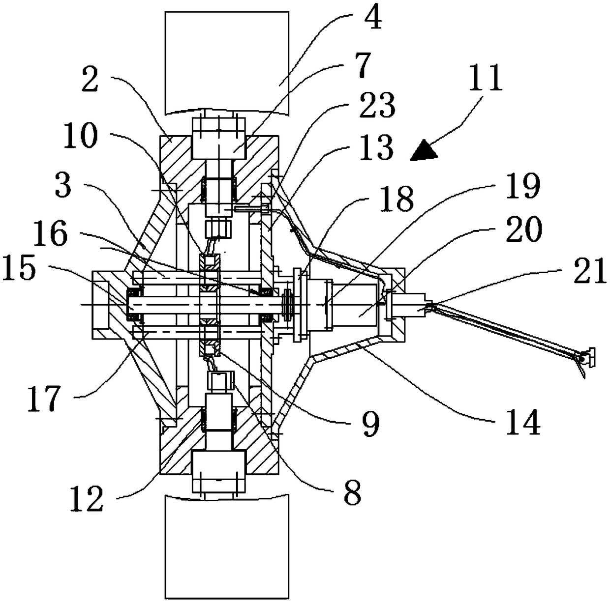
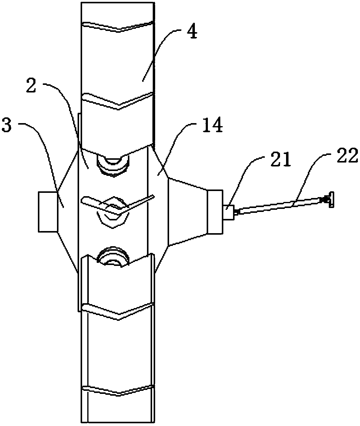
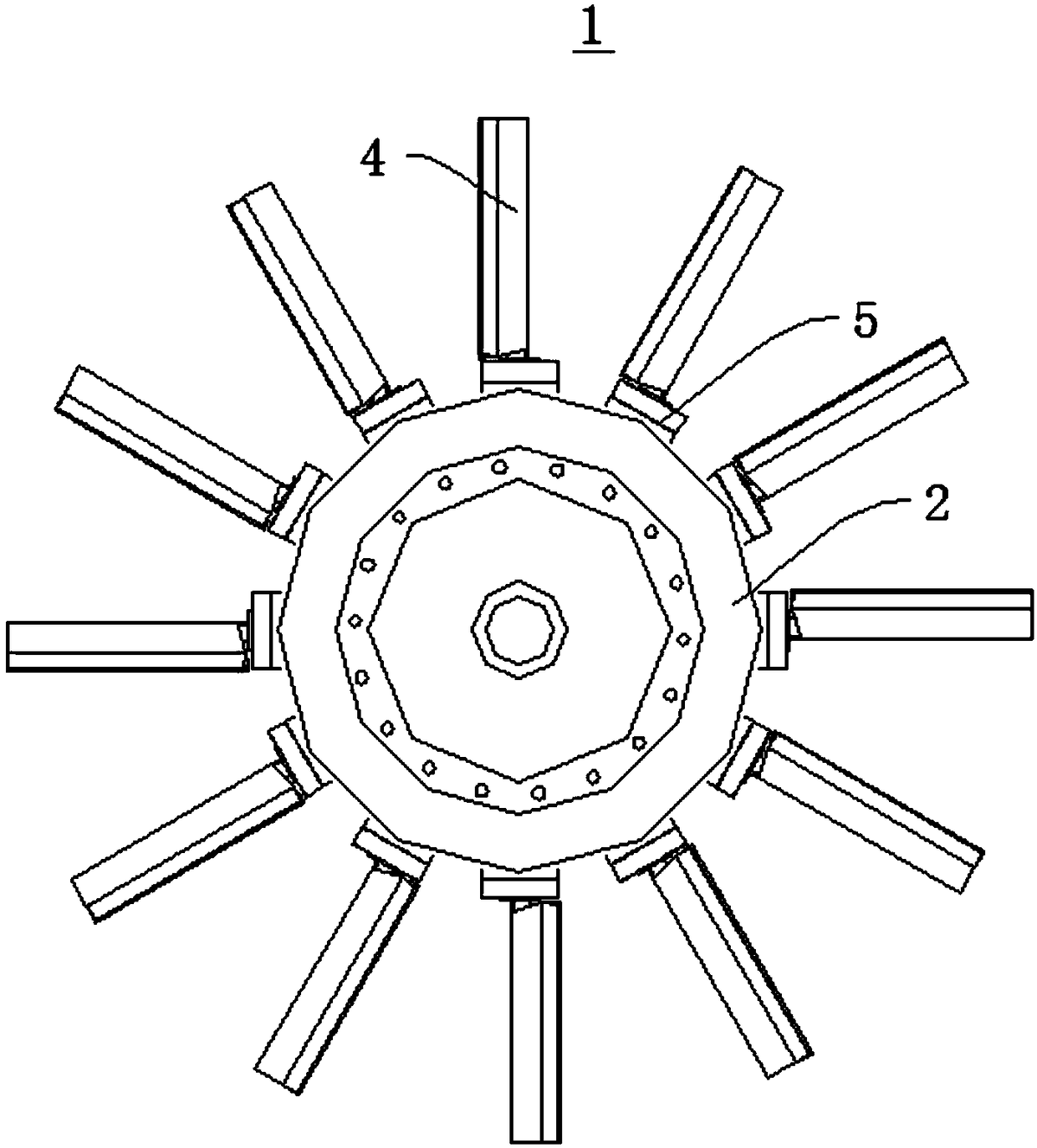
[0040] Please refer to figure 1 , with reference to Figure 2 to Figure 4 The axial flow fan blade adjustment mechanism 1 includes a hub 2, a hub 3, a plurality of blades 4, a transmission assembly 5 and a drive assembly 6; the hub 3 is mounted on the hub 2; the transmission assembly 5 is rotatably mounted on the hub 2, The other end is in transmission connection with a plurality of blades 4; the plurality of blades 4 are evenly distributed along the circumferential direction of the hub 2; the drive assembly 6 is in transmission connection with the transmission assembly 5, and the drive assembly 6 adjusts the plurality of blades by driving the transmission assembly 5 to rotate 4 angles.

[0041] Wherein, the transmission assembly 5 includes a plurality of blade shafts 7, a plurality of cranks 8, a plurality of sliders 9, a pu...


PUM


Abstract

The invention provides an adjustment mechanism for blades of an axial flow fan and the fan and belongs to the technical field of axial flow fans. The adjustment mechanism comprises a hub, a hub disc,multiple blades, a transmission assembly and a driving assembly; the hub disc is installed on the hub; the transmission assembly is rotatably installed on the hub, and the other end of the transmission assembly is in transmission connection with the blades; the blades are evenly distributed in the circumference direction of the hub disc; the driving assembly is in transmission connection with thetransmission assembly, and the driving assembly adjusts the angles of the blades by driving the transmission assembly to rotate. The transmission assembly is arranged in the hub, the driving assemblydrives the transmission assembly to rotate so that the angles of the blades can be adjusted, and the stability of the overall structure is good.

Description

technical field [0001] The invention relates to the technical field of axial flow fans, in particular to an axial flow fan blade adjustment mechanism and a fan. Background technique [0002] Axial flow fans are widely used in industries such as thermal power generation, iron and steel, chemical industry, environmental protection waste gas treatment and other continuous working occasions where the gas flow needs to be dynamically adjusted and changed. When this type of axial flow fan is working, the mechanical energy is converted into gas kinetic energy through the rotation of the impeller; the angle of the guide vane or blade is changed, or the speed of the impeller is changed to control the gas flow. According to whether the angle of the blade changes during operation, it can be divided into two categories: stationary blade fans and movable blade fans, among which the movable blade fans are divided into movable blade adjustable fans and movable blade non-adjustable fans (th...

Claims


Application Information

Patent Timeline
IPC IPC(8): F04D27/00
CPCF04D27/002
Inventor 黄兆飞赵武英赵辉罗建设陈禾怡
Owner CHENGDU TECHCAL UNIV
Why Eureka
Try Eureka