Hydraulic gate valve easy to commission

An easy-to-debug, hydraulic technology, applied in the field of hydraulic gate valves and oil extraction equipment, can solve the problems of failure of the gate valve diameter test, time-consuming and labor-intensive hydraulic gate valves, etc., to improve installation and maintenance efficiency, ensure accuracy, and simple structure. Effect

Pending Publication Date: 2019-01-18
MEIZUAN SHENHAI ENERGY TECH RES & DEV SHANGHAI CO LTD +1
View PDF0 Cites 2 Cited by
  • Summary
  • Abstract
  • Description
  • Claims
  • Application Information

AI Technical Summary

Problems solved by technology

[0004] as attached figure 1 As shown, the valve plate (2') and the valve stem (6') of the common hydraulic gate valve are connected by a T-shaped structure. (6') and bonnet (4') after the conical surface is positioned, the gate valve is just in the fully open state in theory, but due to the influence of mechanical manufacturing tolerances and assembly clearances, sometimes the gate valve diameter test cannot pass
The piston (9.3') in the hydraulic drive hydraulic cylinder drives the movement of the valve plate (2'), the valve stem (6') and the piston (9.3') are connected through the conversion joint (8), and the cylindrical pin fixes the conversion joint (8) and the valve Rod (6'), this connection requires pin holes and drills, resulting in time-consuming and labor-intensive assembly of hydraulic gate valves

Method used


Image

  • Hydraulic gate valve easy to commission
  • Hydraulic gate valve easy to commission
  • Hydraulic gate valve easy to commission

Examples


Embodiment Construction

[0031] In order to make the technical means, creative features, goals and effects achieved by the present invention easy to understand, the present invention will be further described in detail below in conjunction with the accompanying drawings and specific embodiments, but the scope of the present invention is not limited in any way.

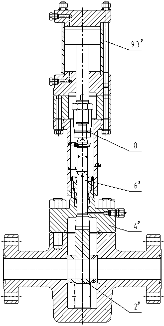
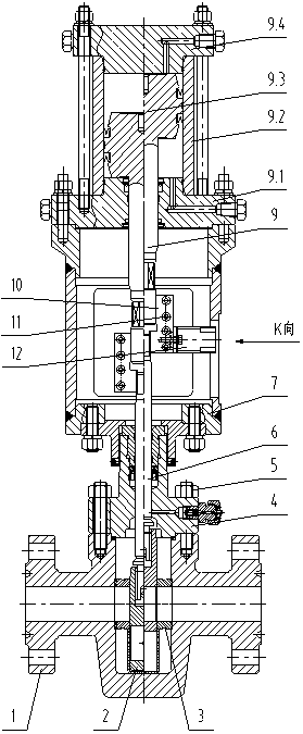
[0032] as attached figure 2 As shown, the valve body (1) and bonnet (4) of the hydraulic gate valve are fixedly connected by bolts (5); there is a sealing groove inside the valve body (1); the upper part of the valve plate (2) is provided with a threaded hole, which is set on The bottom of the sealing groove of the valve body (1) and the bottom of the valve stem (6) are provided with threads, which are threadedly connected with the valve plate (2), and the thread gap between the valve stem (6) and the valve plate (2) is relatively large. The valve seat (3) is arranged in the sealing groove of the valve body (1) and on both sides of the valve ...


PUM


Abstract

The invention discloses a hydraulic gate valve easy to commission. The hydraulic gate valve comprises a valve body, a valve lid, a valve plate, a valve rod, a valve seat, a hydraulic cylinder, connecting blocks, an indicating block, a support, a lower hydraulic cylinder cover, a hydraulic cylinder barrel, a piston and an upper hydraulic cylinder cover, wherein a sealing groove is formed inside thevalve body which is fixedly connected with the valve cover; a threaded hole is formed in the upper portion of the valve plate which is arranged at the bottom of the sealing groove in the valve body;a thread is arranged at the bottom of the valve rod, the valve rod is in threaded connection with the valve plate, and the top of the valve rod penetrates through the valve cover; the valve seat is arranged inside the sealing groove in the valve body and located on the two sides of the valve plate; the first end of the hydraulic cylinder is fixed to the top of the valve rod; the connecting blocksare arranged on the two sides of the connecting position of the hydraulic cylinder and the valve rod to fix the hydraulic cylinder and the valve rod; the indicating block is fixed to the connecting block on one side and provided with an indicator board; the lower end of the support is fixedly connected with the top of the valve cover; the lower hydraulic cylinder cover is fixedly connected with the upper end of the support; the hydraulic cylinder barrel is arranged on the upper portion of the lower hydraulic cylinder cover, and the second end of the hydraulic cylinder penetrates through the lower hydraulic cylinder cover and is arranged inside the hydraulic cylinder barrel; the piston is fixed to the second end of the hydraulic cylinder; the upper hydraulic cylinder cover is arranged on the upper portion of the hydraulic cylinder barrel.

Description

technical field [0001] The invention belongs to oil exploitation equipment, and is an easy-to-adjust hydraulic gate valve, which is mainly used in the fields of high-pressure oil and gas well testing and production engineering. Background technique [0002] As an important part of the Christmas tree and the choke and kill manifold, the gate valve mainly plays the role of cutting off the fluid. [0003] When the gate valve works, it can only have two states of fully open and fully closed. When the valve is half-open and half-closed, the medium will damage the sealing surface of the valve plate and seat. Therefore, in order to ensure that the gate valve is fully open when it is working, the gate valve must be tested for diameter before leaving the factory, that is, the diameter gauge must completely pass through the valve body, valve plate, and valve seat. The manual gate valve adjusts the opening of the valve by rotating the hand wheel, while the hydraulic gate valve drives ...

Claims


Application Information

Patent Timeline
Patent Type & Authority Applications(China)
IPC IPC(8): F16K3/02F16K31/122F16K37/00
CPCF16K3/0254F16K31/122F16K37/0008
Inventor 王志刚
Owner MEIZUAN SHENHAI ENERGY TECH RES & DEV SHANGHAI CO LTD
Why Eureka
Try Eureka