
Air compressor

A technology of air compressors and compressed cylinders, which is applied in mechanical equipment, machines/engines, liquid variable capacity machinery, etc. The effect of the service life

Pending Publication Date: 2019-01-18
浙江藤井空压机有限公司
View PDF1 Cites 2 Cited by
  • Summary
  • Abstract
  • Description
  • Claims
  • Application Information

AI Technical Summary

Problems solved by technology

[0003] During the use of the above-mentioned air compressor, the gas inhaled into the tank will contain moisture, and during the compression of the gas, the moisture will contact the inner wall of the tank and gradually condense into water vapor that sticks to the inside of the tank. On the inner wall of the air compressor, it is easy to corrode the inside of the tank body by water vapor during the long-term use of the air compressor, resulting in a reduction in the service life of the tank body

Method used


Image

  • Air compressor
  • Air compressor
  • Air compressor

Examples


Embodiment Construction

[0031] The present invention will be described in further detail below in conjunction with the accompanying drawings.

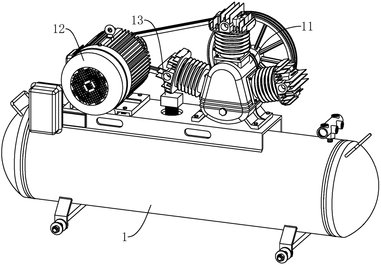
[0032] see figure 1 , an air compressor, comprising a tank body 1, a compression cylinder 11 arranged on the tank body 1, and a drive motor 12, a pressure switch 13 is arranged between the compression cylinder 11 and the drive motor 12, and the two ends of the tank body 1 are arc-shaped shape.

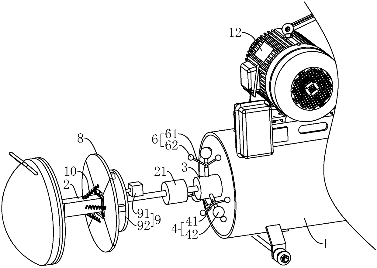
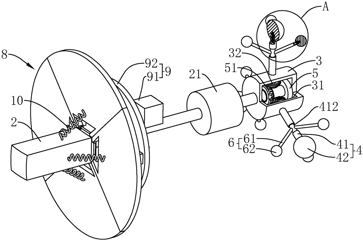
[0033] see figure 2 The two ends of the inner arc shape of the tank body 1 are horizontally equipped with a first cylinder 2, and the end of the output shaft of the first cylinder 2 is fixedly connected with a first motor 21, and the output shaft of the first motor 21 is located at a position away from the first cylinder 2. One side, and the output shaft of the first motor 21 is fixedly connected with the installation block 3, and the outer wall of the installation block 3 is evenly fixed with a number of first dehumidification brushes 4 along the circumferential d...


PUM


Abstract

The invention discloses an air compressor, and relates to the field of air compression. The air compressor comprises a tank body and a compression cylinder arranged on the tank body; a first cylinderis arranged at the inner end of the tank body; a first motor is arranged on an output shaft of the first cylinder; an output shaft of the first motor is located on the side, back away from the first cylinder; a mounting block is fixedly connected with the output shaft of the first motor; a plurality of first dehumidification brushes are arranged on the outer side wall of the mounting block; and each first dehumidification brush comprises a first brush bar connected to the mounting block and a first water absorbing head which wrap around the end of the first brush bar and is attached to the inner side wall of the tank body. Through the arrangement of the first cylinder and the first motor, the first dehumidification brushes rotate along an axial direction of the tank body and rotate along he circumferential direction of the tank body to comprehensively absorb the vapor condensed on the inner side wall of the tank body, thereby decreasing the vapor in the tank body, decreasing the corrosion caused to the inner side wall of the tank body by the water and prolonging the service life of the tank body.

Description

technical field [0001] The invention relates to the field of air compression, in particular to an air compressor. Background technique [0002] The air compressor is a kind of equipment for compressing gas. The existing air compressor is a Chinese utility model patent with the notification number CN205135954U, which discloses an air compressor, including a tank body, on which a A mounting frame, a cylinder for compressing air is fixed on the top of the mounting frame, and a handle for carrying the air compressor is provided at the end of the tank body. [0003] During the use of the above-mentioned air compressor, the gas inhaled into the tank will contain moisture, and during the compression of the gas, the moisture will contact the inner wall of the tank and gradually condense into water vapor that sticks to the inside of the tank. On the inner side wall, the air compressor is easy to be corroded by water vapor during the long-term use of the air compressor, resulting in ...

Claims


Application Information

Patent Timeline
Patent Type & Authority Applications(China)
IPC IPC(8): F17C13/00B01D53/26F04B41/02
CPCB01D53/261F04B41/02F17C13/002F17C2265/015F17C2270/05F17C2221/031F17C2223/0123F17C2201/0109F17C2201/035F17C2201/056B01D2257/80
Inventor 张涛杨树发
Owner 浙江藤井空压机有限公司
Learn More