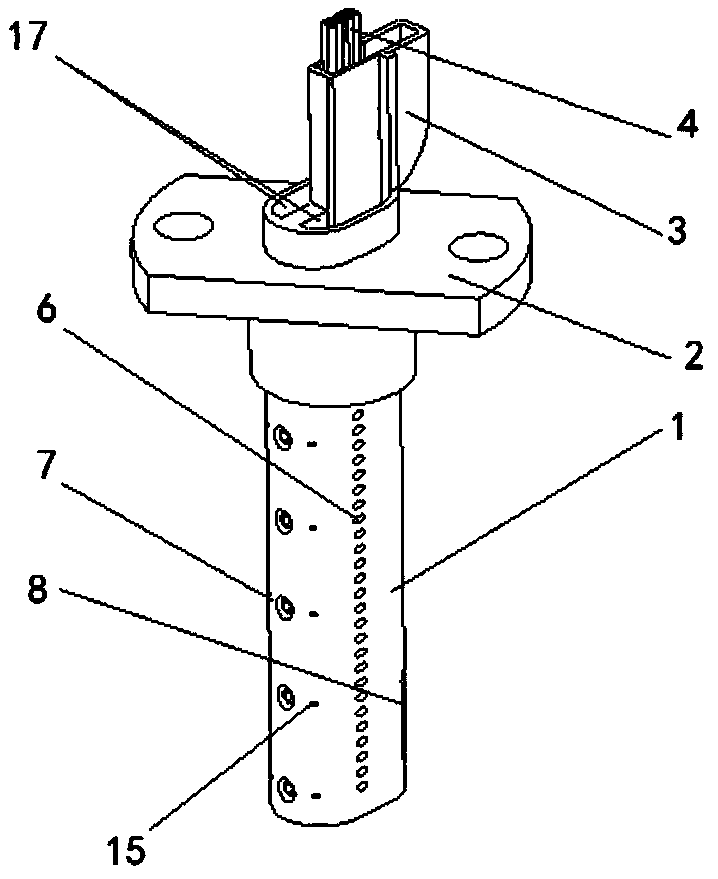
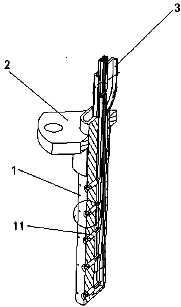
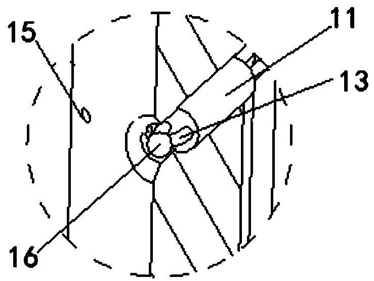
Temperature test receptor part

A technology of measuring points and components, which is applied in the field of high-pressure turbine full-temperature and full-pressure testing, can solve the problems of lack of ability, performance degradation, and damage to structural integrity, and achieves the effect of compact structure and reduced amount of modification.

Inactive Publication Date: 2019-01-18
AECC SHENYANG ENGINE RES INST
View PDF21 Cites 4 Cited by
  • Summary
  • Abstract
  • Description
  • Claims
  • Application Information

AI Technical Summary

Problems solved by technology

[0006] 1. The conventional sensing part is limited by the material, and does not have the ability to work in the high-temperature environment of the high-pressure turbine outlet, and cannot meet the requirements of the full-temperature and full-pressure turbine test
[0007] 2. The existing cooling technology

Method used


Image

  • Temperature test receptor part
  • Temperature test receptor part
  • Temperature test receptor part

Examples


Embodiment Construction

[0039] In order to make the objectives, technical solutions, and advantages of the implementation of the present invention clearer, the technical solutions in the embodiments of the present invention will be described in more detail below in conjunction with the accompanying drawings in the embodiments of the present invention. In the drawings, the same or similar reference numerals indicate the same or similar elements or elements with the same or similar functions. The described embodiments are part of the embodiments of the present invention, but not all of the embodiments. The embodiments described below with reference to the accompanying drawings are exemplary, and are intended to explain the present invention, but should not be construed as limiting the present invention. Based on the embodiments of the present invention, all other embodiments obtained by those of ordinary skill in the art without creative work shall fall within the protection scope of the present inventi...


PUM


Abstract

The invention discloses a temperature test receptor part. The temperature test receptor part comprises a supporting rod module, wherein a cool air chamber, an exhaust chamber and a wiring chamber arearranged in the supporting rod module, cool air holes, measure point holes, exhaust membrane holes, hot gas discharge holes and a tail edge exhaust hole are formed in an outer wall of the supporting rod module, and the measure point holes communicate with the wiring chamber through measure point hole chambers; the cool air holes, the exhaust membrane holes and the tail gas exhaust hole communicatewith the cool air chamber; the hot gas discharge holes communicate with the measure point hole chambers via the exhaust chamber; a sealing-in joint connected with the supporting rod module, wherein acompensation wire chamber is arranged in the sealing-in joint, and the compensation wire chamber communicates with the wiring chamber; thermocouple wire modules arranged in the wiring chamber and themeasure point hole chambers, wherein the thermocouple wire module is provided with a hot-joining point, the hot-joining point is arranged in the measurement point hole chamber and close to the measurement point hole; and a compensation wire arranged in the compensation wire chamber and connected with the thermocouple wire module. The temperature test receptor part disclosed by the application realizes the cooling to the supporting rod through a cooling structure, thereby satisfying a high-temperature test environment demand of a high-pressure turbine.

Description

Technical field [0001] The invention relates to the technical field of a high-pressure turbine full-temperature and full-pressure test, in particular to a temperature test sensing part. Background technique [0002] The high-pressure turbine full-temperature and full-pressure test conducts experimental research on the performance of the high-pressure turbine by simulating the actual working environment of the high-pressure turbine in the aeroengine. In order to obtain the total airflow temperature of the high-pressure turbine flow field, it is necessary to arrange a test sensing part at the outlet of the high-pressure turbine to measure the flow field temperature. The test section has the characteristics of high temperature (maximum temperature up to 1600K), high pressure (maximum pressure up to 1MPa) and high aerodynamic load (air flow Mach number up to 0.6). Therefore, higher requirements are put forward for the structural design of the test sensing part. The air flow tempera...

Claims


Application Information

Patent Timeline
IPC IPC(8): G01K13/02G01K7/02G01M15/02F28D21/00G01K13/024
CPCF28D21/00G01K7/02G01K13/02G01M15/02G01K13/024
Inventor 刘绪鹏张校东王晓良尹东张灿刘国阳邹镇
Owner AECC SHENYANG ENGINE RES INST
Why Eureka
Try Eureka