Rock rheological disturbance effect and step-by-step loading test device
A loading test device and test device technology, applied in the field of rock rheological disturbance test, can solve the problems of high manufacturing cost, high precision requirements of parts and complex system structure, etc.
- Summary
- Abstract
- Description
- Claims
- Application Information
AI Technical Summary
Problems solved by technology
Method used
Image
Examples
specific Embodiment approach 1
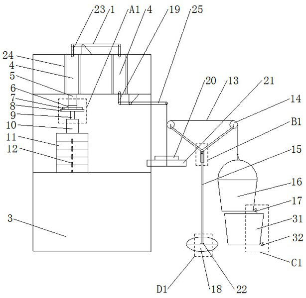
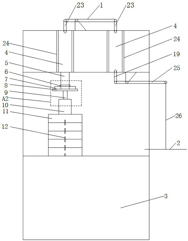
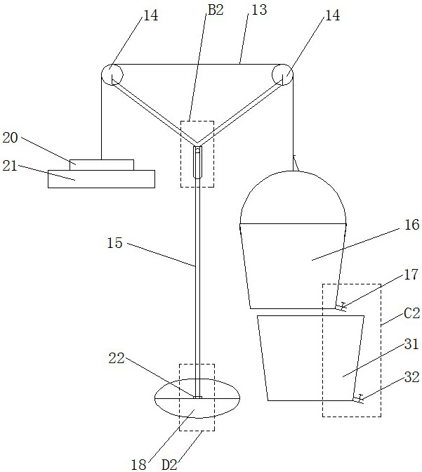
[0023] Specific implementation mode one: as Figure 1-Figure 7 As shown, this embodiment discloses a rock rheological disturbance effect and step-by-step loading test device, which consists of: a rock rheological disturbance effect test device and a step-by-step loading test device; the rock rheological disturbance effect test device includes Loading tray 2, frame body 3, force transmission shaft 5, impact weight 6, disturbance dynamic sensor 7, upper pressure bearing plate 8, pressure sensor 10, connecting rope 26, pad assembly, two sliders 4, two sliders Road 24, two levers and three connecting rods; the two levers are respectively lever one 1 and lever two 25, and the three connecting rods are respectively two connecting rods one 23 and one connecting rod two 19; The step-by-step loading test device includes a force transmission rope 13, a telescopic support 15, a bucket 16, a valve 17, a base 18, a fixed claw 20, a gravity weight 21, a bearing 22 and two fixed pulleys 14; ...
specific Embodiment approach 2
[0042] Specific implementation mode two: as figure 1 , figure 2 As shown, this embodiment is a further description of specific embodiment 1. The backing plate assembly includes a plurality of backing plates 11 and a plurality of fixing nails 12; the plurality of backing plates 11 are stacked in sequence, and each The two backing plates 11 are fixedly connected by fixing nails 12 .
specific Embodiment approach 3
[0043] Specific implementation mode three: as figure 1 , image 3 , Figure 5 , Figure 7 As shown, this embodiment is a further description of specific embodiment 1 or 2. The telescopic bracket 15 includes an outer sleeve 27, an inner sleeve 28, two oblique rods 29 and at least one top wire 30; The tube 27 and the inner casing 28 are set in a set, and the upper end of the outer casing 27 is fixedly connected with the lower ends of the two oblique rods 29. The two oblique rods 29 are arranged symmetrically with respect to the center line of the outer casing 27. The axles of the two fixed pulleys 14 are fixedly connected, and the pipe wall of the outer casing 27 is provided with at least one threaded through hole in the radial direction, and a top wire 30 is screwed in the at least one threaded through hole, and the outer casing 27 passes through the top wire 30 It is firmly connected with the inner sleeve 28 , and the lower end of the inner sleeve 28 is fixedly connected wi...
PUM
 Abstract
Description
Claims
Application Information
 - R&D
- Intellectual Property
- Life Sciences
- Materials
- Tech Scout
- Unparalleled Data Quality
- Higher Quality Content
- 60% Fewer Hallucinations
Browse by: Latest US Patents, China's latest patents, Technical Efficacy Thesaurus, Application Domain, Technology Topic, Popular Technical Reports.
© 2025 PatSnap. All rights reserved.Legal|Privacy policy|Modern Slavery Act Transparency Statement|Sitemap|About US| Contact US: help@patsnap.com


