

Intelligent cooling electric control box and control method thereof
A control method and technology of an electric control box, applied in the field of electric control box, can solve problems such as poor heat dissipation effect, and achieve the effects of improving reliability, optimizing the working environment, and stabilizing the temperature of the working environment
- Summary
- Abstract
- Description
- Claims
- Application Information
AI Technical Summary
Problems solved by technology
Method used
Image

Examples
Embodiment 1
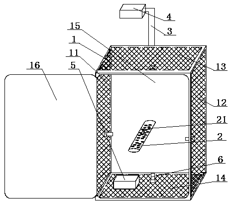
[0053] An intelligent cooling electric control box, comprising a box body 1, a cooling device is arranged inside the box body 1, the cooling device is an air outlet drum 2, and a plurality of air outlets 21 are opened on the air outlet drum 2, the The air inlet end of the air outlet drum 2 is connected with the air outlet end of the air pipe 3, the air inlet end of the air pipe 3 is connected with the air outlet end of the air blower 4, and the control end of the air blower 4 is connected with the controller 5 signal; The inside of the box 1 is provided with at least two temperature sensors 6, and the signal output terminals of the temperature sensors 6 are connected to the controller 5; the left side wall 11 and the right side wall 12 are filter screen structures, and the Both the left side wall 11 and the right side wall 12 are fixed with a temperature sensor 6; the top cover 13 is a filter screen structure, and the top cover 13 is fixed with a temperature sensor 6; the botto...
Embodiment 2
[0059] Embodiment 2 is basically the same as Embodiment 1, and its difference is:
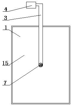
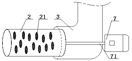
[0060] The electric control box also includes a motor 7, the output shaft of the motor 7 passes through the wall of the air duct 3 and is fixedly connected with the air outlet drum 2, the output shaft of the motor 7 is coaxially arranged with the air outlet drum 2, The air outlet drum 2 is driven and matched with the output shaft of the motor 7, and the air inlet end of the air outlet drum 2 is rotatably matched with the air outlet end of the air duct 3. The diameter of the air outlet end of the air outlet drum 3 is larger than that of the air outlet end of the air outlet drum 2 diameter; the air outlet 21 on the air outlet drum 2 is a porous structure with a filter screen, and the plurality of air outlets 21 are irregularly distributed on the circumferential surface of the air outlet drum 2 .
[0061] The first step of the control method also includes: starting the dust removal when the electr...
Embodiment 3
[0063] Embodiment 3 is basically the same as Embodiment 2, and its difference is:
[0064] Described box body 1 comprises left side wall 11, right side wall 12, top cover 13, bottom plate 14, backboard 15 and front door 16, and the left and right two ends of described top cover 13 pass through left side wall 11, right side respectively. Wall 12 is connected with the left and right ends of base plate 14, and the four sides of described back plate 15 are vertically connected with the rear end of left side wall 11, right side wall 12, top cover 13 and base plate 14 respectively, and described front door 16 is connected with the left side The wall 11 is rotatably matched; the controller 5 is arranged inside the box body 1 .
[0065] The control method also includes a fourth step: regular dust removal. After the blower 4 stops running, the controller 5 starts timing. When the blower 4 is turned on, the timer is reset. 4. Turn on, and control the motor 7 to rotate the air outlet dr...
PUM
 Abstract
Description
Claims
Application Information