
Communication signal filter

A communication signal and filter technology, applied in the field of filters, can solve the problems of metal cavity material loss, incomplete signal filtering, complex structure, etc., and achieve the effect of extending service life, high suppression requirements, and increasing filtering strength.

Inactive Publication Date: 2019-01-18
苏州市矩光达通讯技术有限公司
View PDF0 Cites 0 Cited by
  • Summary
  • Abstract
  • Description
  • Claims
  • Application Information

AI Technical Summary

Problems solved by technology

[0005] The purpose of the present invention is to provide a communication signal filter to solve the problems and deficiencies of the material loss of the metal cavity itself proposed in the above background technology, resulting in incomplete filtering of the signal and complex structure

Method used

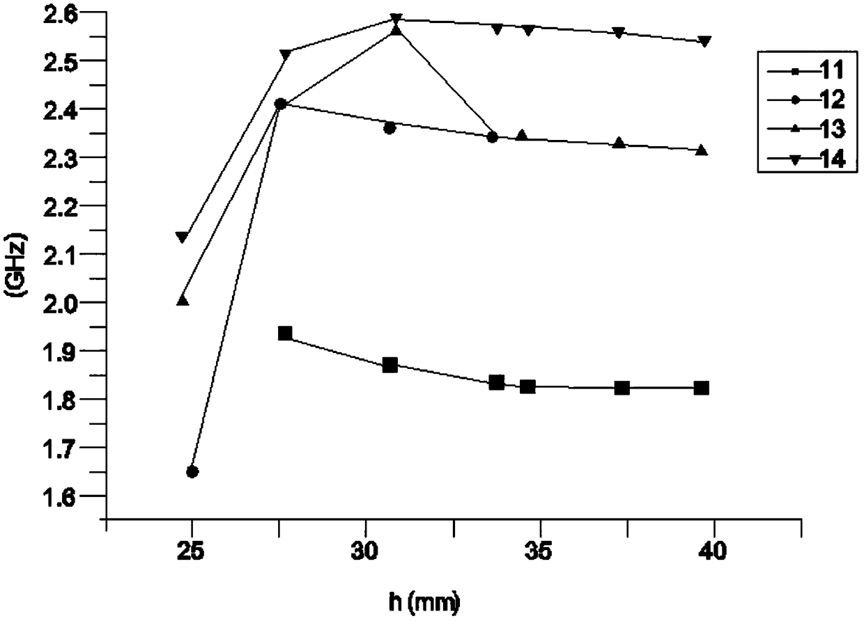
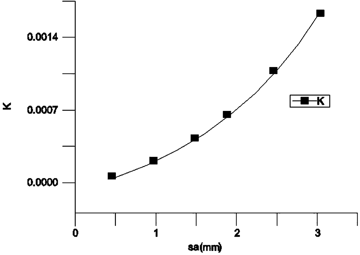

Image

  • Communication signal filter
  • Communication signal filter
  • Communication signal filter

Examples


Embodiment approach

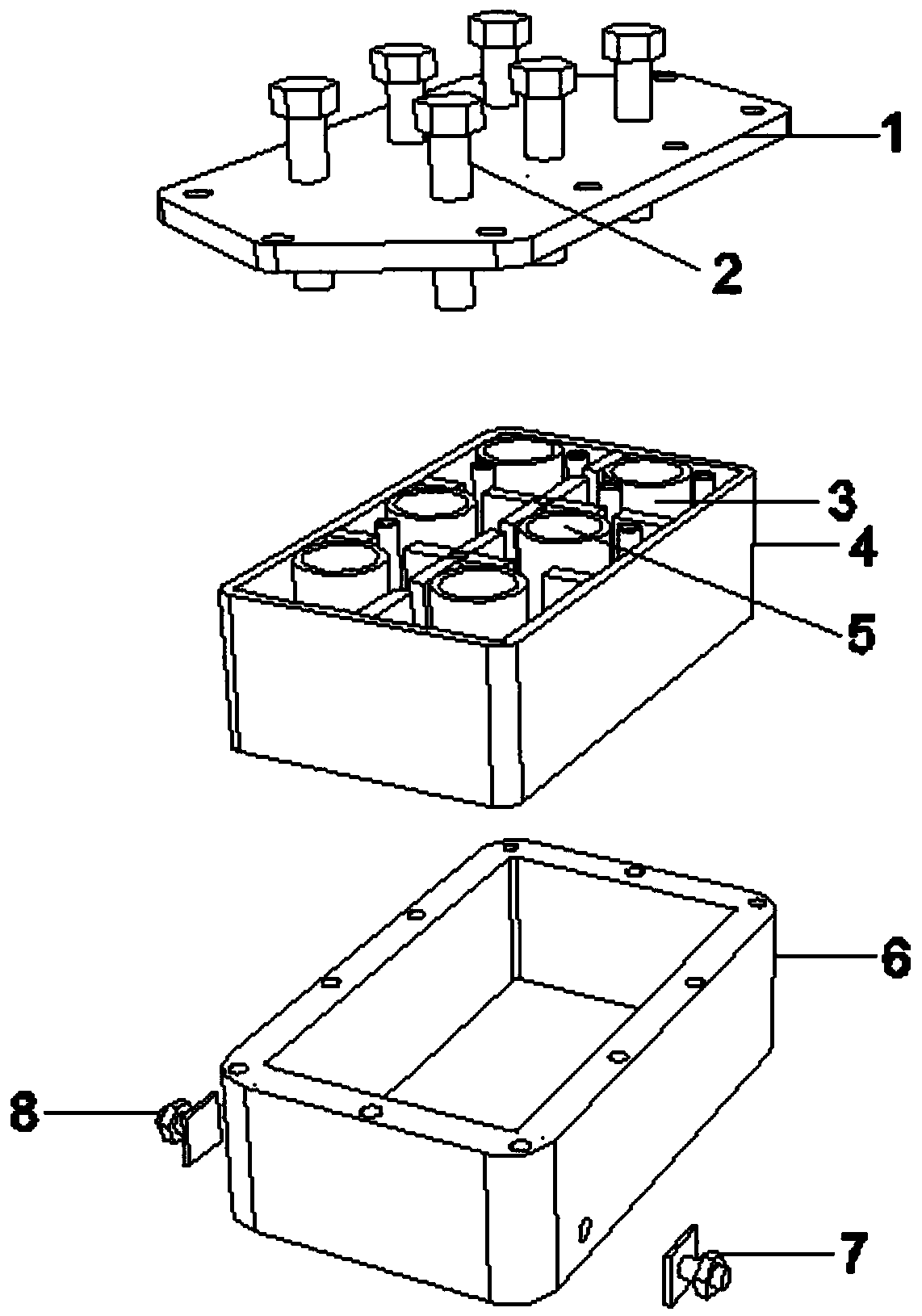
[0026] A communication signal filter, comprising: a cover plate 1, a tuning rod 2, a dielectric 3, a cavity 4, a resonant column 5, a casing 6, an output end 7, and an input end 8; the outer side of the cavity 4 is provided with a casing 6, And the shell 6 is connected with the cavity 4 by means of snap-fitting; the left outer wall of the shell 6 is provided with an input end 8, and one end of the input end 8 is connected with the shell 6 by an inlay; the right outer wall of the shell 6 is provided with an output terminal 7, and the output end 7 is connected to the shell 6 through an inlay method; a resonant column 5 is arranged in the cavity 4, and the resonant column 5 is connected to the cavity 4 through an inlaid method; the outer side of the resonant column 5 is provided with a dielectric 3 , and the electrified medium 3 is connected with the resonant column 5 by fitting; the top side of the cavity 4 is provided with a cover plate 1, and the cover plate 1 is connected with...


PUM


Abstract

The invention relates to a communication signal filter, which comprises a cover plate, a tuning rod, an energizing medium, a cavity, a resonant column, a shell, an output terminal and an input terminal. The outer side of the cavity is provided with a shell, and the shell is connected with the cavity through a clamping mode; The left outer wall of the shell is provided with an input end, and one end of the input end is connected with the shell through a mosaic mode; The right outer wall of the shell is provided with an output end, and the output end is connected with the shell through a mosaicmode; The cavity is provided with a resonant column, and the resonant column is connected with the cavity through a mosaic mode; The outer side of the resonant column is provided with an energizing medium, and the energizing medium is connected with the resonant column through a sleeve mode; The invention has the advantages of reducing the loss, thoroughly filtering and simple structure through the improvement of a communication signal filter, thereby effectively solving the problems and shortcomings proposed in the background of the invention.

Description

technical field [0001] The present invention relates to the technical field of filters, and more specifically, relates to a communication signal filter. Background technique [0002] The signal filter is used to filter out the useful signal from the input signal to filter out the unwanted signal and noise interference. The principle is to use the amplitude-frequency characteristics of the circuit, set the range of its passband to the range of useful signals, and filter out other spectral components. [0003] Traditionally applied filters are generally realized by metal coaxial cavities. Due to the material loss of metal coaxial cavities, in the case of limited cavity size, it is impossible to obtain a high quality factor (Q value), resulting in various All the performance indicators are limited, even if a certain surface treatment is adopted on the metal surface, satisfactory results cannot be obtained. [0004] In view of this, the existing problems are researched and imp...

Claims


Application Information

Patent Timeline
Patent Type & Authority Applications(China)
IPC IPC(8): H01P1/20H01P1/207
CPCH01P1/20H01P1/207
Inventor 杨平易认
Owner 苏州市矩光达通讯技术有限公司
Learn More