
A method and apparatus for protecting microgrid feeder

A feeder protection and micro-grid technology, applied in the direction of emergency protection circuit devices, electrical components, etc., can solve the problems of unreliability and power failure of the whole network, and achieve the effect of ensuring accuracy and reliability, easy implementation, and simple principle

Active Publication Date: 2019-01-18
NR ELECTRIC CO LTD +1
View PDF5 Cites 16 Cited by
  • Summary
  • Abstract
  • Description
  • Claims
  • Application Information

AI Technical Summary

Problems solved by technology

[0005] The purpose of the present invention is to provide a micro-grid feeder protection method to solve the problem that the over-current or directional over-current protection cannot reliably operate when the micro-grid feeder fails, resulting in power loss in the entire network, and at the same time proposes a corresponding micro-grid feeder protection device

Method used


Image

  • A method and apparatus for protecting microgrid feeder
  • A method and apparatus for protecting microgrid feeder
  • A method and apparatus for protecting microgrid feeder

Examples


Embodiment 1

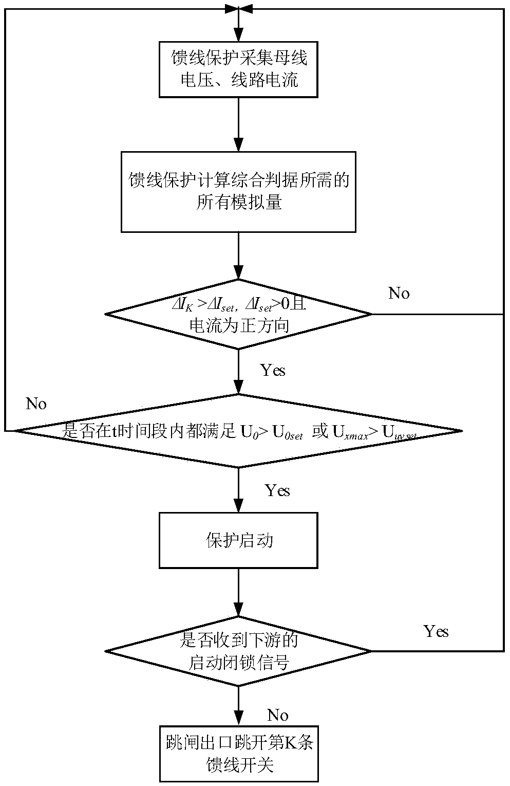
[0051]A microgrid feeder protection method, such as figure 2 In the calculation process shown, the feeder protection device collects the feeder current and bus voltage, receives the protection start GOOSE signal of the downstream protection, starts the feeder protection through the current mutation, and uses the voltage change and current direction as the feeder protection start error setting and the downstream protection start signal The comprehensive criterion for blocking feeder protection action to find out the faulty line is as follows:

[0052] Criterion 1: ΔI k >ΔI set , ΔI set >0 and the current is in the positive direction;

[0053] Criterion 2: U 0 > U 0set or U xmax uvset ;

[0054] Criterion 3: There is no downstream protection or the protection start GOOSE signal sent by the downstream protection is not received.

[0055] Among the above criteria, ΔI k Current sudden change calculated in real time for the kth feeder, ΔI k =I k -I (k-N) , I k The curr...

Embodiment 2

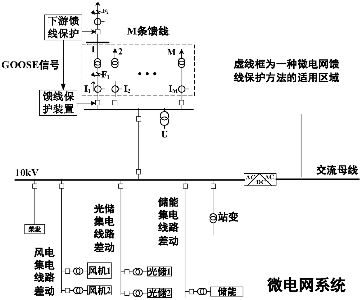
[0063] Such as figure 1 The typical microgrid system shown: the protection device of M feeders collects the three-phase current value and bus voltage of each line, and calculates the current change value ΔI required by the comprehensive criterion of the microgrid feeder protection method k , current direction, maximum bus voltage U between phases xmax and zero sequence voltage U 0 . Each feeder protection receives the protection start signal sent by the downstream protection of the feeder through the IEC61850-GOOSE communication protocol.

[0064] Each feeder protection judges whether the criterion ΔI is satisfied according to the calculation results k >ΔI set , ΔIs et >0 and the current is positive. Taking a single-phase ground fault on feeder 1 as an example, no matter the fault point is at F1 or F2, the current of feeder 1 increases to meet the starting criterion of current variation, and the protection starts, while other feeders such as feeder 2~M are pure load circ...


PUM


Abstract

A method for protecting microgrid feeder includes collecting feeder current and bus voltage, calculating current direction, current variation value and bus zero-sequence voltage value of each feeder,utilizing IEC 61850-GOOSE network communication protocol receives a protection start signal sent by a downstream protection, A sudden change of feed current is adopted to start that protection, the voltage change and current direction are used as the comprehensive criterion to find out the faulty circuit, At the same time, over-current protection is set as backup protection under abnormal communication conditions, which can solve the problem that over-current or directional over-current protection action is not reliable when feeder fault occurs in micro-grid, resulting in power loss of the whole network, and realize fast and accurate fault location and fault tripping isolation. The invention also provides a corresponding feeder protection device.

Description

technical field [0001] The invention relates to the technical field of distributed power generation, and more specifically, to a microgrid feeder protection method and device. Background technique [0002] Microgrid is a small power generation and distribution system composed of distributed power sources, energy storage devices, energy conversion devices, related loads and monitoring and protection devices. It is an autonomous system capable of self-control, protection and management. [0003] Compared with the large power grid, the microgrid has small capacity and poor stability, and contains a large number of power electronic converters. The transient steady state characteristics and short-circuit current characteristics are quite different from the traditional power grid. The particularity of microgrid relay protection is reflected in: 1) Although the voltage level is low, the requirements for quick action of protection are very high. In the event of a short-circuit faul...

Claims


Application Information

Patent Timeline
Patent Type & Authority Applications(China)
IPC IPC(8): H02H7/26
CPCH02H7/26
Inventor 华秀娟徐光福陈俊侯炜
Owner NR ELECTRIC CO LTD
Learn More