Motor housing and motor

A technology for motor shells and casings, which is applied in the direction of casings/covers/supports, electrical components, electromechanical devices, etc., which can solve the problems of thinning spiral channel wall thickness, decreased safety factor, water leakage, etc., to reduce processing costs, Improve stability and avoid structural impact effects

Pending Publication Date: 2019-01-18
GREE ELECTRIC APPLIANCES INC
View PDF0 Cites 1 Cited by
  • Summary
  • Abstract
  • Description
  • Claims
  • Application Information

AI Technical Summary

Problems solved by technology

[0003] However, for the motors of the prior art, the air inlet 5 on the casing 1 communicates radially with the radial ventilation holes 3 on the motor stator, so if it is necessary to ensure that the radial ventilation holes 3 on the motor stator are arranged on the same plane On the other hand, the air intake holes 5 on the casing 1 need to be arranged on the same plane, so the m

Method used


Image

  • Motor housing and motor
  • Motor housing and motor
  • Motor housing and motor

Examples


Embodiment Construction

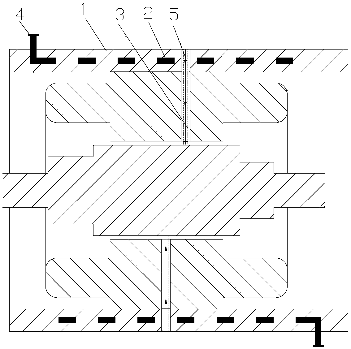
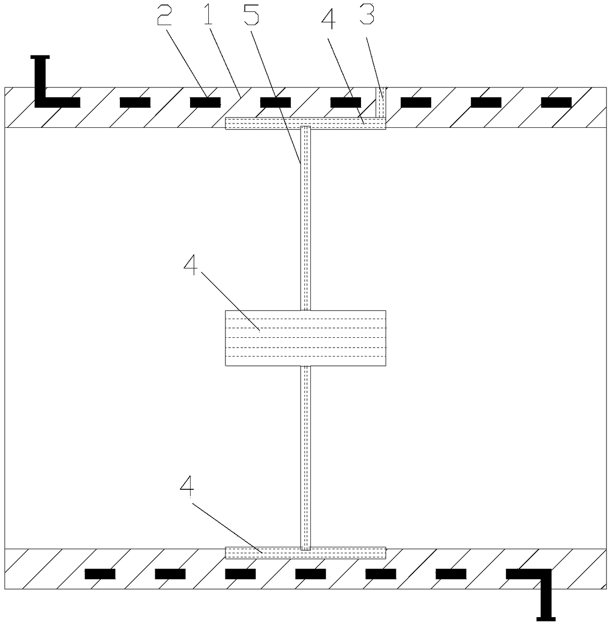
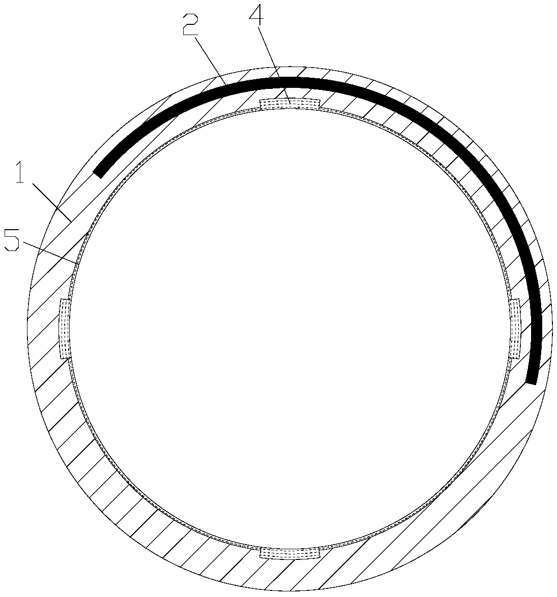
[0023] see in conjunction Figure 2 to Figure 4 As shown, according to the embodiment of the present invention, the motor casing includes a casing 1, and the casing 1 is provided with a spiral water channel 2, an air inlet 3 and a communication channel 4, and the spiral water channel 2 spirally extends along the axial direction of the casing 1, and further The air hole 3 is arranged on the outer surface of the casing 1 and extends radially of the casing 1 . The communication channel 4 is arranged on the inner peripheral side of the spiral water channel 2 and communicates with the air inlet 3 .

[0024] By setting the air intake channel on the casing 1 as a combination of the air intake hole 3 and the communication channel 4, and setting the communication channel 4 on the radial inner side of the spiral water channel 2, the airflow can be conveniently delivered to the The communication channel 4, since the communication channel 4 is arranged on the radial inner side of the spir...


PUM


Abstract

A motor housing and a motor are provided. The motor housing comprises a housing (1); a spiral water channel (2), an air inlet hole (3) and a communication channel (4) are arranged on the housing (1).The spiral water channel (2) extends spirally along the axial direction of the housing (1), the air inlet hole (3) is arranged on the outer surface of the housing (1) and extends radially of the housing (1), and the communication channel (4) is arranged on the inner peripheral side of the spiral water channel (2) and communicates with the air inlet hole (3). According to the motor housing of the invention, the radial ventilation holes on the motor stator can be effectively ensured to be located on the same plane, the structure is simple, and the machining difficulty is low.

Description

technical field [0001] The invention belongs to the technical field of motors, and in particular relates to a motor casing and a motor. Background technique [0002] see figure 1 As shown, the existing high-speed motor cooling structure is composed of 4 parts, 1, casing; 2, spiral water channel; 3, radial ventilation holes; 4 inlet / outlet pipes; 5, air inlet, spiral water channel 2 It is used to cool the stator of the motor, and the radial ventilation holes 4 are used to cool the rotor of the motor; but because the spiral water channel 2 advances in a spiral, the air inlet holes in the circumferential direction of the casing 1 cannot be evenly distributed on the same plane, otherwise they will be pierced waterways leaking, such as figure 1 As shown, the three air inlets 5 are not on one plane among the figure. Since the air intake hole 5 on the casing 1 communicates radially with the radial ventilation hole 3 on the motor stator, if the air intake holes are not on the sam...

Claims


Application Information

Patent Timeline
IPC IPC(8): H02K5/20H02K9/19H02K1/20H02K5/04
CPCH02K5/20H02K1/20H02K5/04H02K9/19
Inventor 闫瑾贾金信张小波刘建宁郭长光李广海魏琼彭利明
Owner GREE ELECTRIC APPLIANCES INC
Why Eureka
Try Eureka