Connection rod small head system with grooves
A technology with small connecting rods and grooves, which is applied in the direction of connecting rods, shafts, bearings, mechanical equipment, etc., can solve the problems of cumbersomeness, increased process costs, and high specific pressure of connecting rod small head bushings, so as to ensure normal application , reduce side load stress, reduce the effect of specific pressure
- Summary
- Abstract
- Description
- Claims
- Application Information
AI Technical Summary
Problems solved by technology
Method used
Image
Examples
Embodiment 1
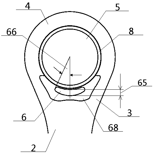
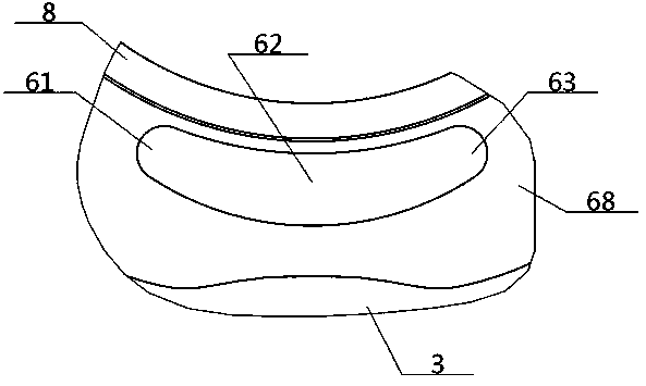
[0047] see Figure 1 to Figure 5 , a grooved connecting rod small head system, comprising a small head end 4 and a central hole 5 opened in the middle, the bottom end of the small head end 4 is connected with the large head end through the shaft 2; the small head end 4 is connected with the large head end; An inner groove 6 is respectively opened on the front side and the back side of the part near the bottom end of the center hole 5 on the upper part 4 , and the inner groove 6 is unidirectionally opened to the outside.
Embodiment 2
[0049] The basic content is the same as that of Example 1, except that:
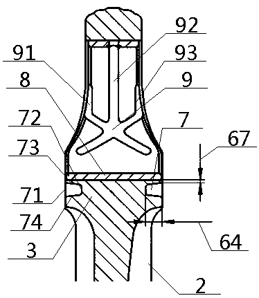
[0050] The inner groove 6 includes a left arc portion 61, a middle arc portion 62 and a right arc portion 63. The right end of the left arc portion 61 is connected to the left end of the right arc portion 63 through the middle arc portion 62. The central axis of 62 coincides with the central axis of the central hole 5, and the left arc portion 61 and the right arc portion 63 are symmetrically arranged with the central axis of the central arc portion 62 as the symmetry line; the left end of the left arc portion 61 is higher than The right end of the right arc portion 63 is set higher than the left end, and the left end of the left arc portion 61 and the right end of the right arc portion 63 are arc structures. Preferably, the cross-section 7 of the inner groove 6 is an isosceles trapezoid structure, which includes an outer edge 71, an inner bottom edge 72, and an upper waist edge 73 and a lower waist edge...
Embodiment 3
[0052] The basic content is the same as that of Example 1, except that:
[0053] The area between the center hole 5 and the shaft 2 on the small end 4 is the rod bearing area 3, and an inner groove 6 is respectively opened on the front and back of the rod bearing area 3; the inner groove 6 The ratio of the groove depth 64 to the width of the rod bearing area 3 is 0.1-0.3, the ratio of the groove width 65 of the inner groove 6 to the radius of the central hole 5 is 0.05-0.1, the left and right ends of the inner groove 6 and the central hole 5 The center lines respectively intersect to form length angles 66, the length angles 66 being 45°-60° in size. The edge distance 67 between the upper edge of the inner groove 6 and the bottom edge of the central hole 5 is 1-3 mm.
PUM
 Abstract
Description
Claims
Application Information
 - R&D
- Intellectual Property
- Life Sciences
- Materials
- Tech Scout
- Unparalleled Data Quality
- Higher Quality Content
- 60% Fewer Hallucinations
Browse by: Latest US Patents, China's latest patents, Technical Efficacy Thesaurus, Application Domain, Technology Topic, Popular Technical Reports.
© 2025 PatSnap. All rights reserved.Legal|Privacy policy|Modern Slavery Act Transparency Statement|Sitemap|About US| Contact US: help@patsnap.com


