A permanent magnet motor with long service life

A permanent magnet motor, long-life technology, used in synchronous motors with static armatures and rotating magnets, electrical components, electromechanical devices, etc. Reduce overheating damage, increase service life and reduce wear and tear

Inactive Publication Date: 2019-01-22
CHANGZHOU INST OF TECH
View PDF6 Cites 0 Cited by
  • Summary
  • Abstract
  • Description
  • Claims
  • Application Information

AI Technical Summary

Problems solved by technology

[0002] The permanent magnet synchronous motor is a synchronous motor that is excited by a permanent magnet to generate a synchronous rotating magnetic field. The permanent magnet acts as a rotor to generate a rotating magnetic field. The three-phase stator winding reacts through the armature under the action of the rotating magnetic field to induce a three-phase symmetrical current; Magneto, designed as a motor protector, its temperature sensing device is mainly to detect the temperature sensed by the motor to the casing. When the motor is overheated and sensed to the temperature sensor on the casing, the internal components of the motor may have burned. Bad, that is, the motor induction is not sensitive, and the protector cannot respond or alarm in time, so that even if the traditional motor is installed with a protector, there is still a phenomenon of overheating and burning. The oil cannot completely enter the components of the motor, resulting in incomplete refueling or even oil leakage. In the traditional motor design, due to the integrated design of the motor shaft, the motor shaft in the motor has a very large cycle effect. It is easy to have a large stress concentration phenomenon, which makes the shaft produce fatigue cracks, which eventually leads to damage to the parts and greatly reduces the service life of the motor

Method used


Image

  • A permanent magnet motor with long service life
  • A permanent magnet motor with long service life
  • A permanent magnet motor with long service life

Examples


Embodiment Construction

[0021] The preferred embodiments of the present invention are described in detail below with reference to the accompanying drawings, so that the advantages and features of the present invention can be more easily understood by those skilled in the art, and the protection scope of the present invention can be more clearly defined.

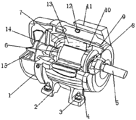
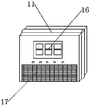
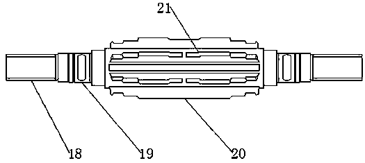
[0022] see Figure 1-3 , The present invention provides a technical solution: a permanent magnet motor with a long service life, comprising a motor body 1, a motor support 2, a fixing bolt 3, a motor casing 4, a motor shaft 5, a rotor 6, a stator 7, a buffer cushion 8. Oil tank 9, built-in monitor 10, motor protector 11, oil filling hole 12, permanent magnet magnetic stage 13, built-in oil pipe 14, cooling fan 15, display panel 16, alarm 17, tandem shaft section 18, bearing support point 19. The motor shaft 20 and the oil passage 21, the outer side of the motor body 1 is provided with a motor housing 4, the bottom end of the motor housing 4 is provi...


PUM


Abstract

The invention discloses a permanent magnet motor with long service life, including a motor body, the outside of the motor body is provided with a motor shell, A motor support is arranged at the bottomend of the motor shell, the middle end of the motor support is provided with a fixing bolt, A top middle end of the motor shell is provided with an oil filling hole, A motor protector is arranged atthe top end of the motor shell, A display panel is arranged in the middle of one end of the motor protector, the bottom end of the display panel is provided with an alarm, An oil groove is arranged onthe inner side of the motor housing, A motor shaft is arranged in the middle of the side end of the motor body, The built-in sensor is arranged on the side of the rotor winding, and the temperature sensor can detect the temperature of the rotor winding, so that the detection is more sensitive, and the connected motor protectors are more sensitive, and can respond to the overheating more quickly,so that the overheating damage of the motor can be reduced to a certain extent, and the service life of the motor is prolonged.

Description

technical field [0001] The invention relates to the technical field of permanent magnet motors, in particular to a permanent magnet motor with long service life. Background technique: [0002] A permanent magnet synchronous motor is a synchronous motor that generates a synchronous rotating magnetic field by excitation of a permanent magnet. The permanent magnet acts as a rotor to generate a rotating magnetic field, and the three-phase stator windings react through the armature under the action of the rotating magnetic field to induce a three-phase symmetrical current. Magneto, designed as a motor protector, its temperature sensing device mainly detects the temperature sensed by the motor to the casing. When the motor is overheated and sensed by the temperature sensor on the casing, the components inside the motor may have been burned. Damage, that is, the motor is not sensitive, and the protector cannot respond or alarm in time, so that the traditional motor still has the ph...

Claims


Application Information

Patent Timeline
Patent Type & Authority Applications(China)
IPC IPC(8): H02K5/04H02K11/25H02K7/00H02K21/14
CPCH02K5/04H02K7/003H02K11/25H02K21/14
Inventor 俞霖廉春原庄华鲍静益邵春声
Owner CHANGZHOU INST OF TECH
Why Eureka
Try Eureka