Liquid stirring oscillation device, application and liquid stirring method

An oscillation device and liquid technology, which is applied in the field of liquid stirring and liquid stirring oscillation device, can solve the problems such as inability to react to solution stirring

Active Publication Date: 2019-01-25
INST OF HIGH ENERGY PHYSICS CHINESE ACADEMY OF SCI
View PDF17 Cites 3 Cited by
  • Summary
  • Abstract
  • Description
  • Claims
  • Application Information

AI Technical Summary

Problems solved by technology

[0003] The technical problem to be solved by the present invention is: for the special reaction environment and the reaction pool of narrow size, the reaction solution cannot be stirred by the conventional stirring method

Method used


Image

  • Liquid stirring oscillation device, application and liquid stirring method
  • Liquid stirring oscillation device, application and liquid stirring method
  • Liquid stirring oscillation device, application and liquid stirring method

Examples


Embodiment 1

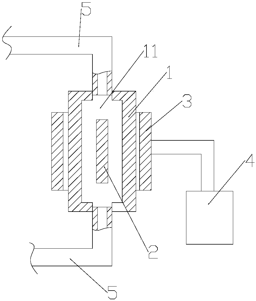
[0028] refer to figure 1 , this embodiment discloses an oscillating device for stirring a liquid, which is connected to a reactor (not shown in the figure) and stirs the liquid in the reactor. The oscillating device includes an isolation body 1 , an inner core 2 , a magnetic jacket 3 , a power source 4 and a connecting pipe 5 .

[0029] The isolator 1 is a columnar body made of Hastelloy, and a flow channel 11 is formed on the isolator 1 . In this embodiment, the isolator 1 is cylindrical, the flow channel 11 is linear, and the flow channel 11 is arranged coaxially with the isolator. The inner core 2 is cylindrical and located in the flow channel 11 .

[0030] The magnetic jacket 3 is a hollow cylinder whose inner diameter is adapted to the outer diameter of the separator 1 ; the magnetic jacket 3 is sheathed on the outer surface of the separator 1 and attracts the inner core 2 .

[0031] The power source 4 is connected with the magnetic jacket 3 to drive the magnetic jacke...

Embodiment 2

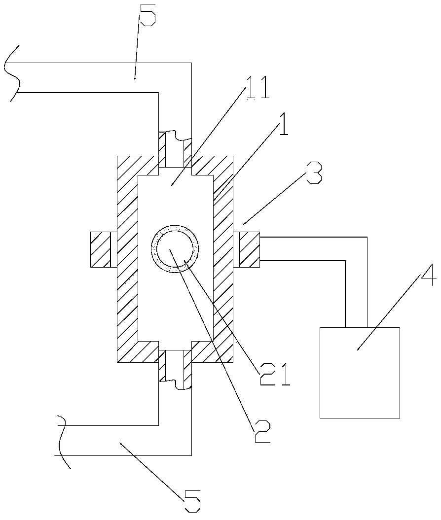
[0039] refer to figure 2 The difference between this embodiment and embodiment 1 is that the inner core 1 is spherical, and its surface is provided with a corrosion-resistant layer 21, which is made of polytetrafluoroethylene material, so as to prevent the inner core 2 from being corroded. and pollute the liquid; the magnetic jacket 3 is in the shape of a ring.

Embodiment 3

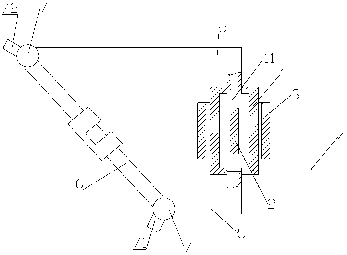
[0041] The capillary 6 with a diameter of about 1 mm is often used as a liquid sample detection cell in the field of X-ray measurement, and the liquid in it needs to be stirred in order to increase the experimental signal intensity during the detection process. In this embodiment, the oscillating device described in Embodiment 1 is used to realize the stirring of the liquid in the capillary 6 .

[0042] refer to image 3 , the end of the capillary 6 is connected to the connection pipeline 5 respectively by two three-way valves 7, and a sample inlet 71 is set at one three-way valve 7, and a sample outlet 72 is set at another three-way valve 7, of course, When stirring, both the sample inlet 71 and the sample outlet 72 are closed. After the reaction solution fills the channel 11, the linear motor is turned on to vibrate and stir the reaction solution in the capillary 6.

[0043] During the experiment, it can be determined whether to pressurize or locally heat the liquid in the...


PUM


Abstract

The invention discloses a liquid stirring oscillation device. The liquid stirring oscillation device is used for stirring liquid in reactors and comprises an isolation body, a magnetic jacket, an inner core, a power source and connecting pipelines. The isolation body is in the shape of a columnar body, a flow channel is formed on the isolation body and is provided with two ports, and the two portsare positioned on two end surfaces of the isolation body; the magnetic jacket sleeves the outer surface of the isolation body; the inner core is positioned in the flow channel and can be attracted bythe magnetic jacket to move along with the magnetic jacket; the power source is connected with the magnetic jacket, and the magnetic jacket can be driven by the power source to carry out reciprocating linear movement on the isolation body along the axis of the isolation body; the flow channel can be connected with the reactors by the connecting pipelines; closed circuits are formed by the connecting pipelines, the flow channel and the reactors. The invention further discloses application of the liquid stirring oscillation device and a liquid stirring method. The liquid stirring oscillation device, the application and the liquid stirring method have the advantages that the liquid in the reactors can be stirred in external back-and-forth oscillation modes, and the liquid stirring oscillation device and the liquid stirring method are free of influence of the spatial sizes and layout of the reactors, the reaction temperatures, the pressures and atmosphere and are widely applicable to diversified reaction systems.

Description

technical field [0001] The invention belongs to the technical field of chemical experiment devices, and in particular relates to an oscillation device for liquid stirring, its application and a liquid stirring method. Background technique [0002] In chemical reactions, stirring the solution is a routine requirement for many experiments. Usually, liquid stirring in chemical experiments is achieved by magnetic stirrer or external mechanical stirring, however, magnetic stirrer cannot be used to achieve stirring in reaction vessels under some special conditions. For example, under ultra-high temperature reaction conditions, the stirrer will lose its magnetism due to high temperature; in a closed liquid with a certain pressure or a special atmosphere, external stirring is powerless; in a narrow reaction space, such as a capillary temperature-pressure pool with a diameter of only 1mm, When it is not possible to put a magnetic stirrer or an external stirring device, the mixing an...

Claims


Application Information

Patent Timeline
Patent Type & Authority Applications(China)
IPC IPC(8): B01F13/08
CPCB01F33/453B01F2101/23
Inventor 默广吴忠华郑黎荣邢雪青蔡泉姚磊施展李志宏陈中军
Owner INST OF HIGH ENERGY PHYSICS CHINESE ACADEMY OF SCI
Why Eureka
Try Eureka