Al technical title is built by PatSnap Al team. It summarizes the technical point description of the patent document.
A dispensing machine and electronic technology, applied in the field of dispensing machines, can solve problems such as large dispensing position errors, large dispensing position errors, and easy sliding of the worktable, so as to reduce dispensing errors, improve airtightness, and improve The effect of dispensing effect
Inactive Publication Date: 2019-01-25
NANJING INST OF RAILWAY TECH
View PDF9 Cites 2 Cited by
Summary
Abstract
Description
Claims
Application Information
AI Technical Summary
This helps you quickly interpret patents by identifying the three key elements:
Problems solved by technology
Method used
Benefits of technology
Problems solved by technology
[0004] 1. The outflow of glue in the above-mentioned dispensing machine requires the staff to start the pressure device. The operation is random and the error is large, resulting in a large error in the dispensing position
[0005] 2. The adjustment of the position of the workbench on the conveyor is mainly...
Method used
Image
Click on the blue label to locate the original text in one second.
Reading with bidirectional positioning of images and text.
Examples
Embodiment Construction
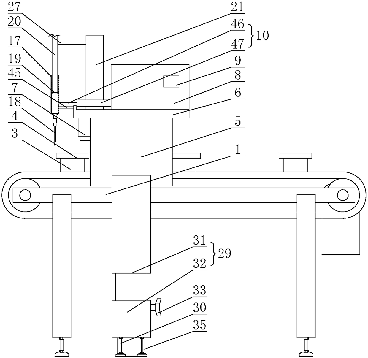
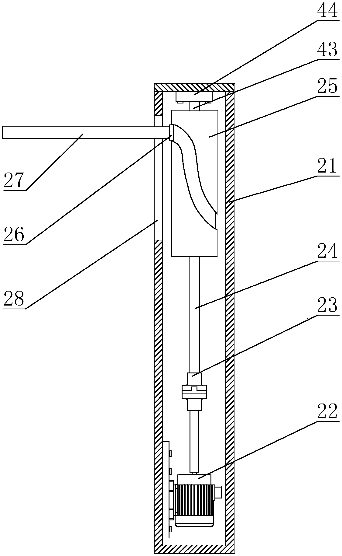
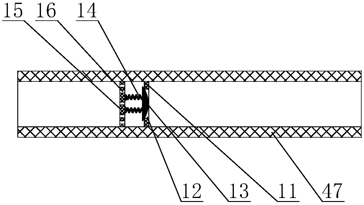
[0032] The present invention will be further described in conjunction with the accompanying drawings and specific embodiments. It should be understood that these examples are only used to illustrate the present invention and are not intended to limit the scope of the present invention. In addition, it should be understood that after reading the content taught by the present invention, those skilled in the art may make various changes or modifications to the present invention, and these equivalent forms also fall within the scope defined in the present application.
[0033] The standard parts used in the present invention can be purchased from the market, and the special-shaped parts can be customized according to the instructions and the accompanying drawings. The specific connection methods of each part adopt mature bolts, rivets, welding in the prior art , pasting and other conventional means, the circuit connections adopted are all conventional models in the prior art, and ...
PUM
Abstract
The invention discloses an electronic automatic dispensing machine and relates to a dispensing machine. The electronic automatic dispensing machine comprises a conveyor, wherein grooves are formed ina conveyor belt of the conveyor; distances among the plurality of grooves are equal; the grooves are internally provided with supporting seats; a worktable is arranged on the supporting seats; the supporting seats are detachably and fixedly connected with the worktable; the conveyor is provided with a portal frame; a supporting frame is arranged on the portal frame; a first shell body is arrangedon the supporting frame; the first shell body and a connection pipe are located at the same side of a glue box; a first motor is arranged at the bottom of an inner wall of the first shell body; a first rotating rod is arranged at one end, far away from an output shaft of the first motor, of a first shaft coupler; a cylindrical cam shaft is arranged at one end, far away from the first shaft coupler, of the first rotating rod; a cylindrical cam roller is arranged in an annular cam groove of the cylindrical cam shaft; a transmission rod is arranged on the cylindrical cam roller; a third through hole is formed in the first shell body; one end of the transmission rod is fixedly connected with a push rod. The electronic automatic dispensing machine disclosed by the invention has the beneficial effects that an existing dispensing machine is improved, dispensing errors are reduced and the dispensing effect is improved.
Description
technical field [0001] The invention mainly relates to a glue dispensing machine, in particular to an electronic automatic glue dispensing machine. Background technique [0002] Glue dispensing machine, also known as glue applicator, glue dropping machine, glue machine, glue pouring machine, etc., is an automatic machine that controls the fluid, and drips and coats the fluid on the surface of the product or inside the product, which can realize three-dimensional and four-dimensional Path dispensing, precise positioning, precise glue control, no stringing, no glue leakage, no glue dripping. The glue dispenser is mainly used for accurate pointing, injecting, coating, and dripping of glue, paint and other liquids in the product process to the precise position of each product, and can be used to achieve dots, lines, circles or arcs. [0003] In the prior art, for the dispensing of simple workpieces, the patent ZL 201711174312.4 discloses an electronic automatic dispensing machi...
Claims
Application Information
Patent Timeline
Application Date:The date an application was filed.
Publication Date:The date a patent or application was officially published.
First Publication Date:The earliest publication date of a patent with the same application number.
Issue Date:Publication date of the patent grant document.
PCT Entry Date:The Entry date of PCT National Phase.
Estimated Expiry Date:The statutory expiry date of a patent right according to the Patent Law, and it is the longest term of protection that the patent right can achieve without the termination of the patent right due to other reasons(Term extension factor has been taken into account ).
Invalid Date:Actual expiry date is based on effective date or publication date of legal transaction data of invalid patent.