Polishing machine used for polishing upper and lower groove bodies

A grinding machine and tank technology, which is applied to grinding frames, grinding machine parts, grinding machines, etc., can solve the problems of interference of fixture grinding parts, low grinding efficiency and low degree of automation, so as to prolong equipment adjustment and realize The effect of automation degree and high automation rate

Pending Publication Date: 2018-10-16
SUZHOU RS TECH
View PDF7 Cites 1 Cited by
  • Summary
  • Abstract
  • Description
  • Claims
  • Application Information

AI Technical Summary

Problems solved by technology

[0002] On the non-standard automatic processing line, it is often necessary to use a grinder to grind and polish the processed workpiece to meet the designed surface roughness. The parts of the workpiece that need to be polished are the upper and lower surface grooves. The existing grinding The structure of the machine is complex, the degree of automation is low, and there are many steps that require manual assistance, resulting in low grinding efficiency and low grinding accuracy. In addition, the existing grinding machines still lack the ability to stably clamp the workpiece without affecting the grinding efficiency. The carrier mechanism makes the workpiece easy to loosen during the grinding process, or the fixture interferes with the grinding part, which further leads to low grinding accuracy and low grinding efficiency

Method used


Image

  • Polishing machine used for polishing upper and lower groove bodies
  • Polishing machine used for polishing upper and lower groove bodies
  • Polishing machine used for polishing upper and lower groove bodies

Examples


Embodiment Construction

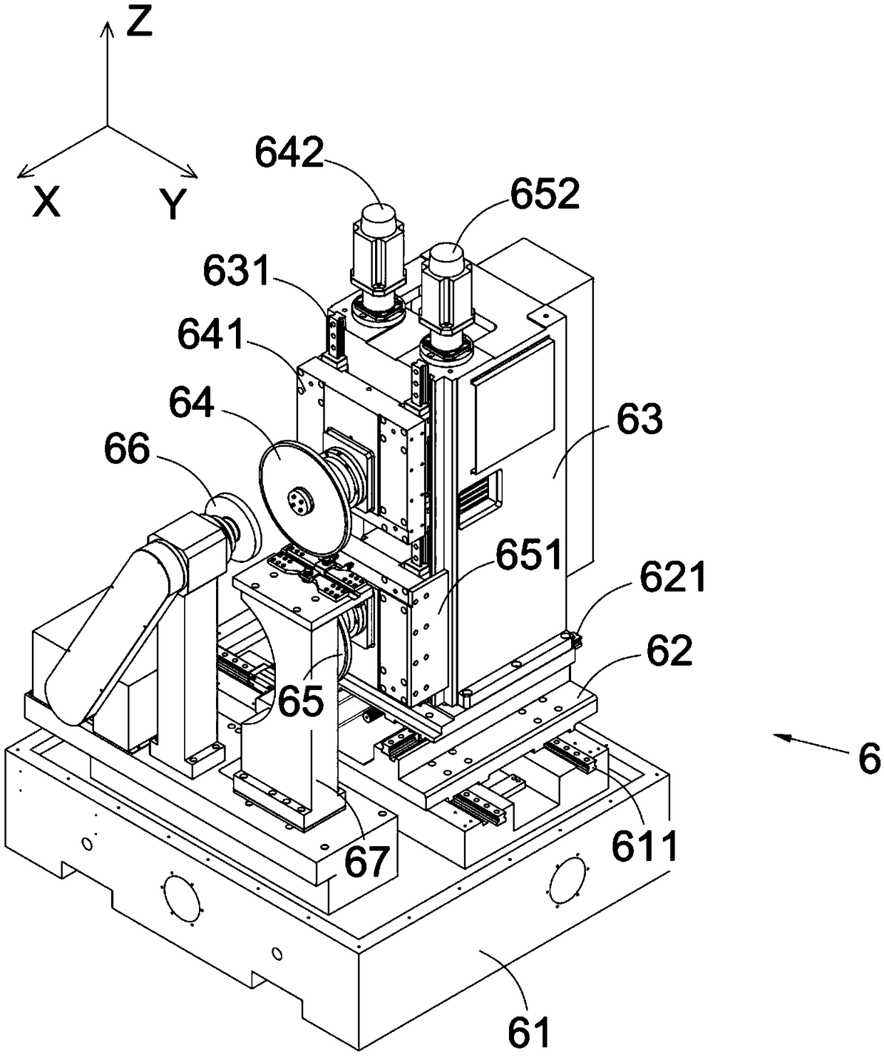
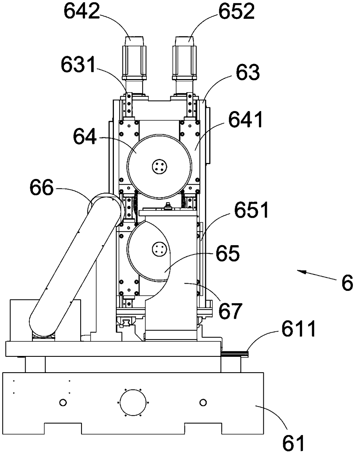
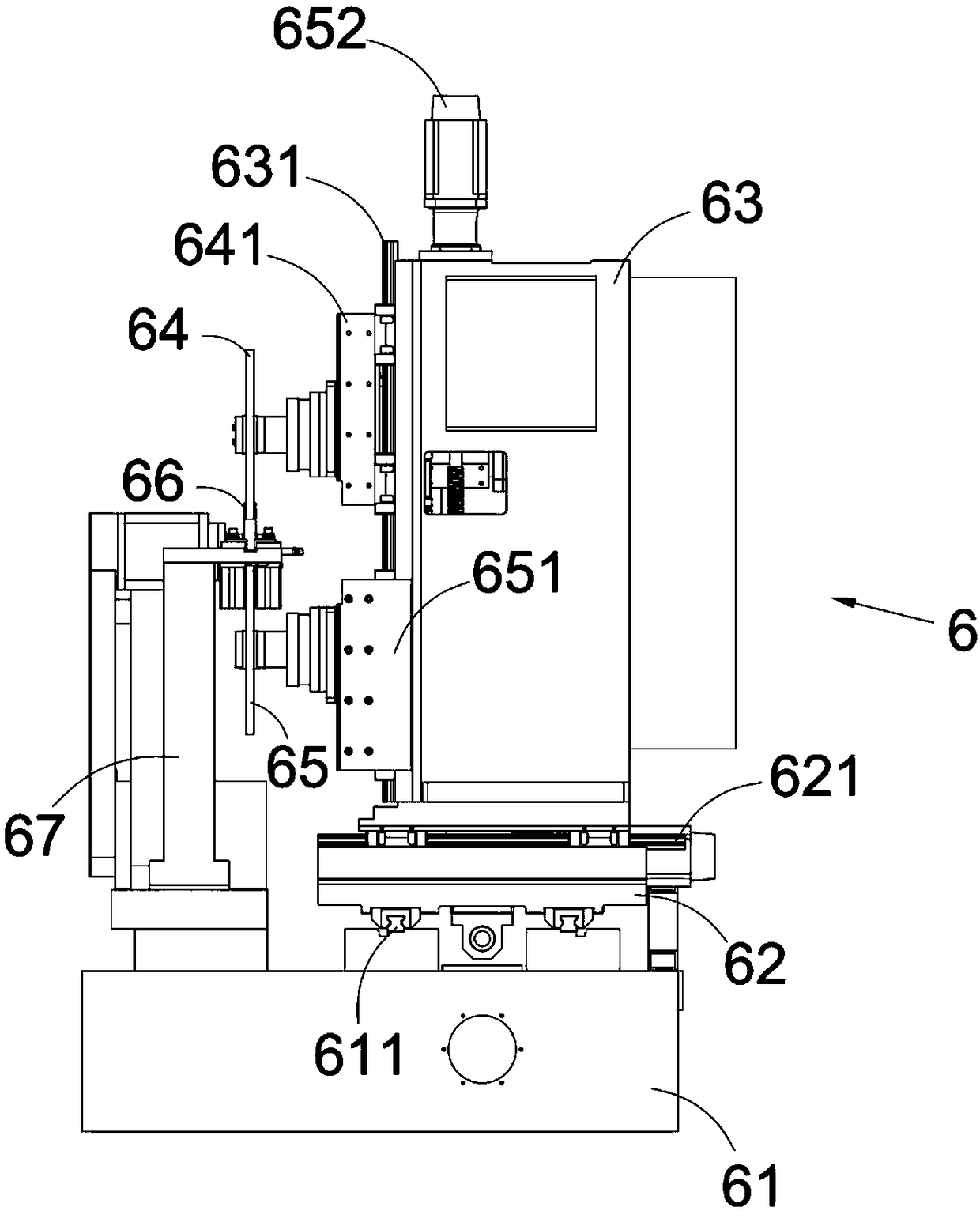
[0042] The present invention will be further described in detail below in conjunction with the accompanying drawings, and the aforementioned and other objects, features, aspects and advantages of the present invention will become more apparent, so that those skilled in the art can implement them with reference to the description. In the drawings, the shapes and dimensions may be exaggerated for clarity, and the same reference numerals will be used throughout to designate the same or like parts. In the following description, terms such as center, thickness, height, length, front, back, rear, left, right, top, bottom, upper, lower, etc. are based on the orientation or positional relationship shown in the drawings. In particular, "height" corresponds to the dimension from top to bottom, "width" corresponds to the dimension from left to right, and "depth" corresponds to the dimension from front to back. These relative terms are for convenience of description and are generally not ...


PUM


Abstract

The invention discloses a polishing machine used for polishing upper and lower groove bodies. The polishing machine comprises a fixing base, a connection base in sliding connection with the upper portion of the fixing base, and an abrasive disk mounting base in sliding connection with the upper portion of the connection base, wherein an upper abrasive disk assembly and a lower abrasive disk assembly which are arranged oppositely up and down are arranged on the same side face of the abrasive disk mounting base; and a carrying table mechanism used for bearing to-be-polished workpieces is arranged on the front side of the upper abrasive disk assembly and the lower abrasive disk assembly. The polishing machine is small in size and compact in structure, has high automation rate, can stably clamp the to-be-polished workpieces, can also achieve automation degree of clamping and polishing of the workpieces, and can also improve the matching degree of the clamping procedure and the polishing procedure. In addition, abrasive disks can be trimmed online after being abraded, the equipment adjustment and maintenance period is prolonged, the polishing precision and efficiency are greatly improved, and wide market application prospects are achieved.

Description

technical field [0001] The invention relates to the field of non-standard automation, in particular to a grinding machine for grinding upper and lower tank bodies. Background technique [0002] On the non-standard automatic processing line, it is often necessary to use a grinder to grind and polish the processed workpiece to meet the designed surface roughness. The parts of the workpiece that need to be polished are the upper and lower surface grooves. The existing grinding The structure of the machine is complex, the degree of automation is low, and there are many steps that require manual assistance, resulting in low grinding efficiency and low grinding accuracy. In addition, the existing grinding machine still lacks the ability to stably clamp the workpiece without affecting the grinding efficiency. The carrier mechanism makes the workpiece easy to loosen during the grinding process, or the fixture interferes with the grinding part, which further leads to low grinding acc...

Claims


Application Information

Patent Timeline
Patent Type & Authority Applications(China)
IPC IPC(8): B24B27/00B24B41/00B24B41/06B24B41/02B24B47/06B24B53/12B24B19/02
CPCB24B19/02B24B27/0076B24B41/005B24B41/02B24B41/06B24B47/06B24B53/12
Inventor 吴加富缪磊马纪飞郭依优王跃跃
Owner SUZHOU RS TECH
Why Eureka
Try Eureka