Gear aligning mechanism

A technology of movable top and indicator plate, which is applied in the direction of metal processing machinery parts, metal processing, automatic control devices, etc., can solve the problems of multiple tooling and processes, inability to adjust the deviation value, and inconvenient maintenance, etc., to achieve the goal of locking The effect of simple tightening method, simple structure and low cost

Pending Publication Date: 2019-01-25
浙江中智鲸工智能装备有限公司
View PDF9 Cites 0 Cited by
  • Summary
  • Abstract
  • Description
  • Claims
  • Application Information

AI Technical Summary

Problems solved by technology

However, this method cannot quantitatively adjust the deviation value for each batch of workpieces, and the methods currently on the market have restrictions on the sequence of each process, and in order to meet the workpiece head and tail spline tooth, spline opposite groove, spline For the phase angle relationship such as flat position, the sequence of the process needs to be adjusted, and there are more tooling and processes
[0003] Or use the servo motor to drive and adjust, and then cooperate with the principle of angle induction to solve the problem of tooth alignment accuracy, but the cost of this tooth alignment method is too high, and the later maintenance is inconvenient

Method used


Image

  • Gear aligning mechanism
  • Gear aligning mechanism

Examples


Embodiment Construction

[0024] The present invention will be further described below in conjunction with specific embodiment:

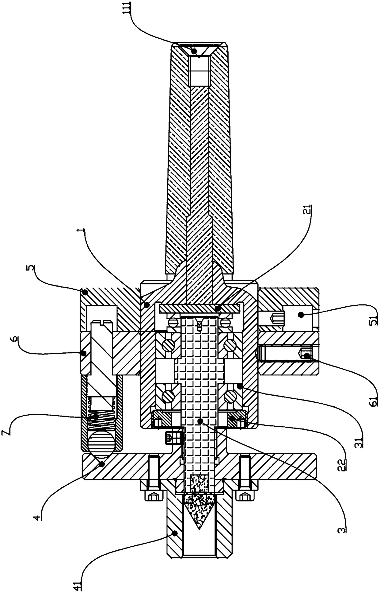
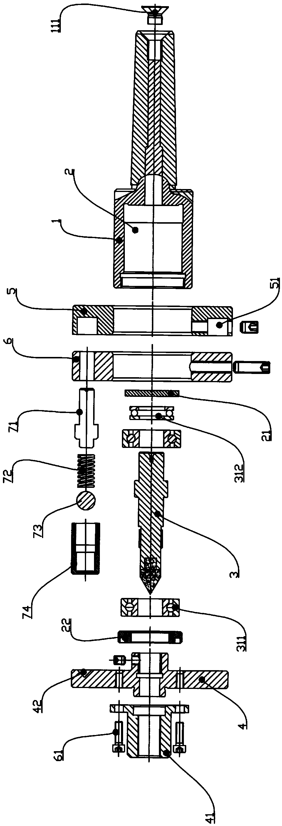
[0025] Such as Figure 1-2 As shown, a tooth-aligning mechanism includes a movable top shell 1, and one end of the movable top shell 1 is formed with an installation cavity 2, and a top shaft 3 is rotatably arranged in the installation cavity 2, and one end of the top shaft 3 is sleeved for Connect the positioning plate 4 of the workpiece, the right side of the movable top shell 1 is sleeved with a dial 5 and an indicator plate 6, and the indicator plate 6 is set to rotate relative to the dial 5; There is an elastic limiter 7, the elastic limiter 7 is in movable abutment with the positioning plate 4, and a locking screw 61 is screwed inside the indicator plate 6, and the locking screw 61 is used to abut against the movable top A locking indicator plate 6 is realized on the outer periphery of the shell 1 .

[0026] In actual use, a product is generally processed first for a ...


PUM


Abstract

The invention belongs to the technical field of machine tool processing, in particular to a gear aligning mechanism which comprises a movable apex shell, wherein an installation cavity is formed at one end of the movable top shell, a apex shaft, wherein the apex shaft is rotationally arranged in the installation cavity, a positioning disc, wherein the positioning disc for connecting a work-piece is sleeved at one end of the apex shaft. The right side of the movable apex shell is sleeved with a dial and an indicating disc, and the indicating disc is rotationally arranged relative to the dial. An elastic limiting device is arranged between the indicating disc and the positioning disc, wherein the elastic limiting device is movably abutted against the positioning disc. A locking screw is screwed in the indicating disc, and the locking screw is used for locking the indicating disc by abutting against the outer periphery of the movable apex shell. The gear aligning mechanism has the advantages of simple structure, low cost, simple operation, adjustable bias value, high gear aligning precision, convenient maintenance and the like.

Description

technical field [0001] The invention belongs to the technical field of machine tools, in particular to a gear alignment mechanism. Background technique [0002] With the rapid development of economy and technology, the market demand continues to expand, and the automation industry has also achieved rapid development. The center line of the tooth and the groove often deviates when the teeth and teeth, teeth and grooves are matched, but at present, when processing products that need to be aligned, two equipments are generally used for processing, and the design fixture corresponding to each equipment To achieve tooth alignment. However, this method cannot quantitatively adjust the deviation value for each batch of workpieces, and the methods currently on the market have restrictions on the sequence of each process, and in order to meet the workpiece head and tail spline tooth, spline opposite groove, spline For the phase angle relationship such as flat position, the sequence...

Claims


Application Information

Patent Timeline
Patent Type & Authority Applications(China)
IPC IPC(8): B23Q15/22B23Q15/26
CPCB23Q15/22B23Q15/26
Inventor 赵亚飞
Owner 浙江中智鲸工智能装备有限公司
Why Eureka
Try Eureka