Horizontal oil cylinder hydraulic machine
A hydraulic machine and oil cylinder technology, applied in the field of hydraulic pressure, can solve the problems of high investment cost, heavy tonnage, complicated manufacturing, etc., and achieve the effect of reducing manufacturing cost, saving site space, and occupying a small space for equipment
- Summary
- Abstract
- Description
- Claims
- Application Information
AI Technical Summary
Problems solved by technology
Method used
Image

Examples
Embodiment 1
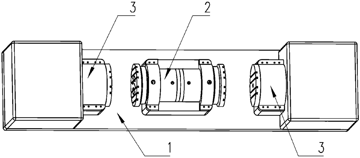
[0040] Such as figure 1 As shown, a horizontal cylinder hydraulic machine described in this embodiment includes a support assembly 1, a main cylinder device 2, a single-sided support table assembly 3, the support assembly 1 serves as a support base, the main cylinder device 2, a single-sided support The support workbench components 3 are all installed on the support component 1, wherein a single-sided support workbench component 3 is respectively installed at both ends of the support component 1. It should be noted that the two single-side support workbench components here are 3 are made of the same material and made by the same process, so as to ensure that the two single-sided supporting workbench assemblies 3 can bear the same pressure.
[0041] The main oil cylinder device 2 is arranged between the two single-sided support workbench assemblies 3, especially, the main oil cylinder is located at the midpoint of the two, the main oil cylinder device 2 includes two main oil cy...
Embodiment 2
[0045] Such as figure 1 , Figure 7As shown, this embodiment is a further limitation of the first embodiment above. In this embodiment, the hydraulic machine also includes a slide rail 4. The slide rail 4 is arranged on the support assembly 1. The main cylinder device 2 is slidably connected to the support assembly 1 through the slide rail 4. . Wherein, the sliding direction of the slide rail 4 is the same axial direction as the telescopic direction of the piston rod 24 of the main oil cylinder device 2, and the slide rail 4 is formed by arranging a number of sticks side by side. Preferably, there are two slide rails 4, and the support assembly 1 supports the main The position of the oil cylinder device 2 is a concave structure, which is attached to the outer wall of the main oil cylinder, and the slide rail 4 is embedded on the concave wall. During work, the piston rods 24 of the two main oil cylinders are stretched and pressed together. Due to the slidability of the main o...
Embodiment 3
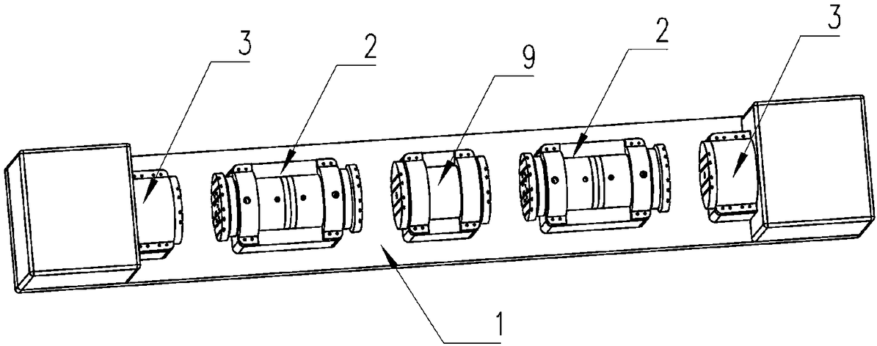
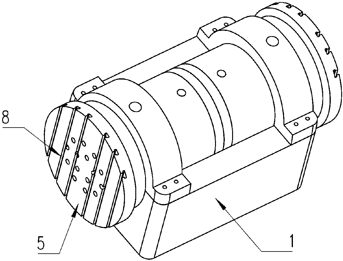
[0047] Such as Figure 2 to Figure 7 As shown, a horizontal cylinder hydraulic machine described in this embodiment includes a support assembly 1, a main cylinder device 2, a support workbench device, and a slide rail 4, wherein the main cylinder includes two sets of back-to-back master cylinders, and the master cylinder There is one or a group of one-way piston rods 24, wherein the main oil cylinder includes an oil cylinder liner 21, an oil cylinder front cover 22, an oil cylinder rear cover 23, and a piston rod 24. The oil cylinder liner 21 is cylindrical, and the oil cylinder front cover 22 and the oil cylinder rear The covers 23 are all circular, and the oil cylinder front cover 22 and the oil cylinder back cover 23 block the two ends of the oil cylinder liner 21 respectively. Pass through the through hole of the piston rod 24.
[0048] The support workbench device comprises a single-sided support workbench assembly 3, a double-side support workbench assembly, and a movab...
PUM
 Abstract
Description
Claims
Application Information
 - R&D
- Intellectual Property
- Life Sciences
- Materials
- Tech Scout
- Unparalleled Data Quality
- Higher Quality Content
- 60% Fewer Hallucinations
Browse by: Latest US Patents, China's latest patents, Technical Efficacy Thesaurus, Application Domain, Technology Topic, Popular Technical Reports.
© 2025 PatSnap. All rights reserved.Legal|Privacy policy|Modern Slavery Act Transparency Statement|Sitemap|About US| Contact US: help@patsnap.com