Fluid blowing roller

A fluid injection and fluid technology, applied in furnaces, heat treatment equipment, coiled strips, etc., can solve the problems of reducing the productivity of high-strength and ultra-high-strength steel plates, and achieve the effects of eliminating instability, reducing vibration, and preventing damage

Active Publication Date: 2019-01-25
浦项控股股份有限公司 +1
View PDF8 Cites 0 Cited by
  • Summary
  • Abstract
  • Description
  • Claims
  • Application Information

AI Technical Summary

Problems solved by technology

However, this method has a problem of greatly reducing the productivity of high-strength ultra-high-strength steel sheets

Method used


Image

  • Fluid blowing roller
  • Fluid blowing roller
  • Fluid blowing roller

Examples


Embodiment Construction

[0051] Embodiments of the present invention will be described in detail below with reference to the drawings. The following embodiments are only proposed to fully convey the idea of ​​the present invention to those skilled in the art. The invention is not limited to the embodiments presented here, but may be embodied in other forms. In order to clarify the present invention, the figures that are not relevant to the description are omitted from the drawings, and the size of components may be slightly exaggerated to facilitate understanding.

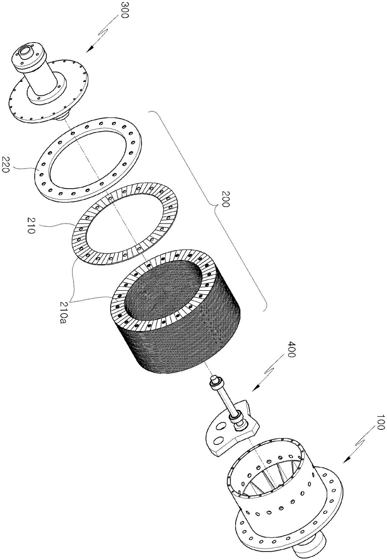
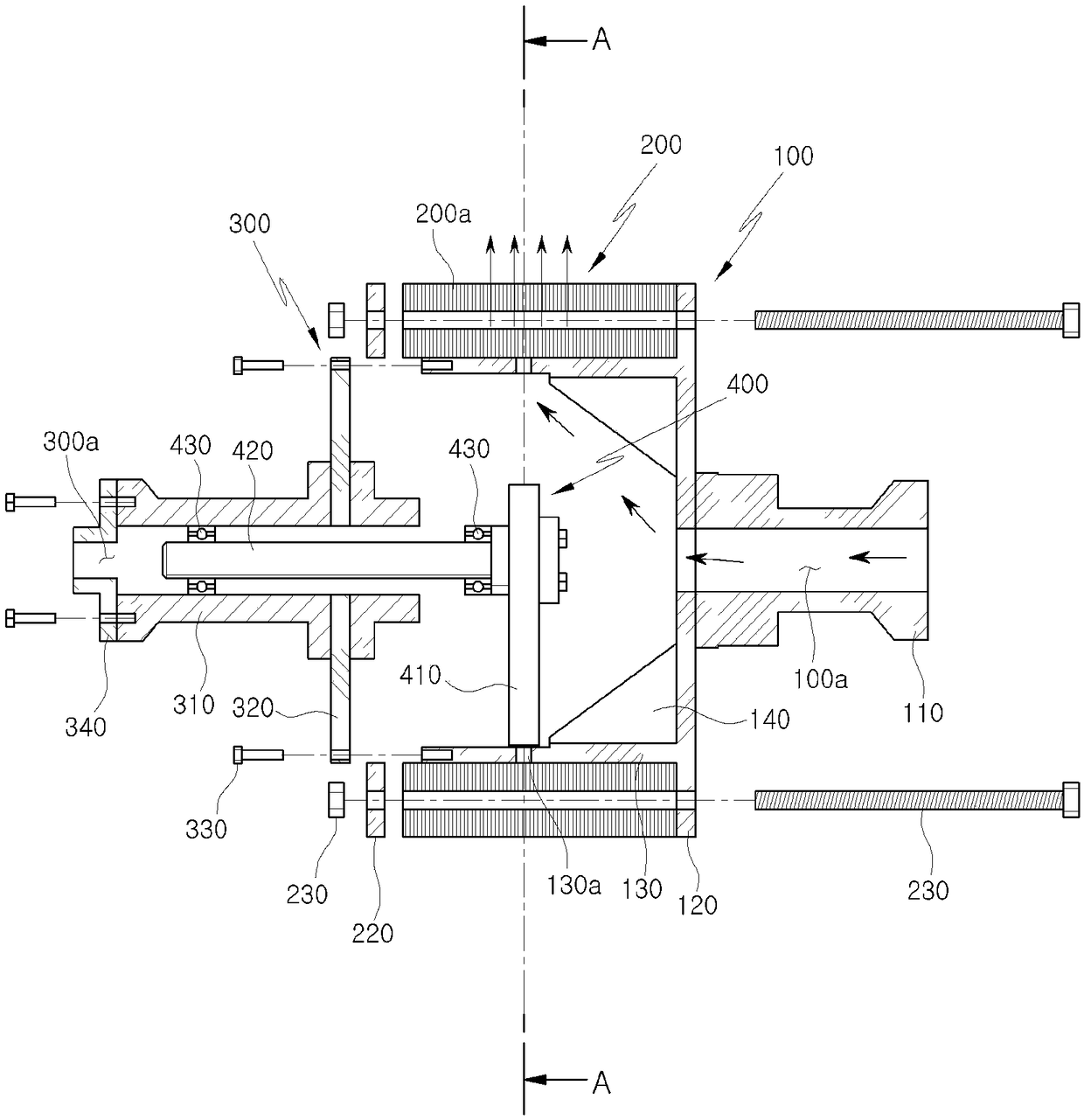
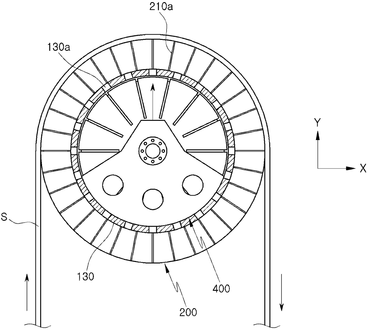
[0052] figure 1 is a structural diagram of a fluid ejection roller 10 according to an embodiment of the present invention, figure 2 is a side sectional view of a fluid ejection roller 10 according to an embodiment of the present invention, image 3 is for figure 2 A cross-sectional view of line A-A. and, Figure 4 It is a figure which shows the simulation result of the vortex which generate|occur|produces around the fluid ejection ...


PUM


Abstract

The fluid blowing roller of the present invention includes a rotating unit having a through hole formed on an outer circumferential surface; a disk unit fastened to an outer circumferential surface ofthe rotating unit and having an outlet for discharging fluid flowing in from the through hole to the outside; a blocking unit disposed inside the rotating unit to block the flow of a fluid of a portion of the through hole.

Description

technical field [0001] The present invention relates to a fluid jetting roll capable of conveying steel plates or plates without causing wear. Background technique [0002] Following the trend of strengthening safety regulations worldwide, automobile companies are expanding the use of high-strength steel in order to reduce fuel consumption and ensure crash stability. For this reason, steel companies use a method of increasing the strength of steel by using a phase transformation structure in order to manufacture high-strength steel. This is because it is difficult to cope with this tendency only by existing mechanisms such as solid solution strengthening and precipitation strengthening. [0003] In order to increase the strength of steel utilizing a transformation structure, it is necessary to add a large amount of alloy elements such as Si, Mn, and Cr. However, Si, Mn, etc. are oxidizing elements, which combine with oxygen during the hot rolling process and continuous ann...

Claims


Application Information

Patent Timeline
Patent Type & Authority Applications(China)
IPC IPC(8): C21D9/63
CPCC21D9/562C21D9/63B65H23/24B65H27/00B65H2406/15B65H2701/173
Inventor 宋吉镐宋龙燮
Owner 浦项控股股份有限公司
Why Eureka
Try Eureka