
Curved bridge step pushing method

A curved bridge and jacking technology, which is applied in bridges, bridge construction, erection/assembly of bridges, etc., can solve problems such as unsatisfactory, low efficiency, and inability to run at a loading speed

Active Publication Date: 2019-01-25
GUANGDONG CONSTR CO LTD OF CHINA RAILWAY NO 3 ENG GRP CO LTD +2
View PDF7 Cites 8 Cited by
  • Summary
  • Abstract
  • Description
  • Claims
  • Application Information

AI Technical Summary

Problems solved by technology

However, this method has disadvantages: when the curve is adjusted, the jacking operation must be interrupted, and the jacking process is intermittent, and the efficiency is low
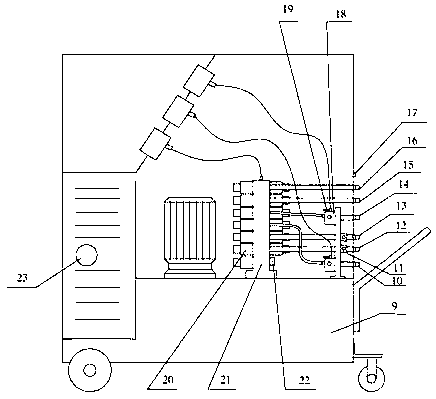
[0003] The applicant has been authorized and the patent No. ZL201620588250.6 is the patent "Pumping Station of Walking Pushing System", which discloses a pumping station of walking pushing system, which can realize vertical lifting system, longitudinal pushing system, The dynamic deviation correction system and other subsystems are integrated together, and one system can meet the functions of vertical lifting, vertical and horizontal pushing and horizontal automatic deviation correction, but this equipment has certain limitations: although the same pumping station can control multiple jacks, but the loading speeds of multiple jacks of the same model working at the same time are basically the same, and they cannot run at different loading speeds at the same time, so they cannot meet the requirements of automatic pushing according to the arc curve.

Method used


Image

  • Curved bridge step pushing method
  • Curved bridge step pushing method
  • Curved bridge step pushing method

Examples


Embodiment Construction

[0022] The present invention comprises steps:

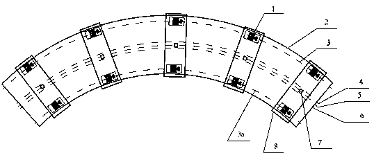
[0023] (1) Calculation steps: According to the curvature and radius of the main girder’s pushing route, calculate the total distance of the outer pushing and the total distance of the inner pushing respectively, determine the speed ratio of the pushing on both sides according to the distance, and determine the pushing on both sides according to the speed ratio The oil inlet flow ratio of the jack;

[0024] (2) Control center parameter setting steps: set in the control center including the oil inlet flow ratio of the jacks on both sides, the maximum allowable deviation distance of the main girder, and the relevant parameters of jacking, pushing, and deviation correction. After the setting is completed start the device;

[0025] (3) Arrangement steps of jacking units: set multiple groups of jacking units on both sides of the pier inside and outside. , arranged in the center along the tangential direction;

[0026] (4) Steps for ...


PUM


Abstract

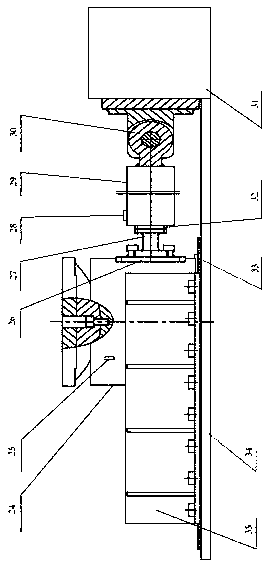
The invention relates to a curved bridge step pushing method. Pluralities of sets of pushing units are arranged on the outer side of a pier and on the outer side of the pier. The pushing units are arranged on the circular curves with equal distances on both sides of the bridge centerline, namely, the outer pushing trajectory line and the inner pushing trajectory line, and are centrally arranged along a tangential direction. An electro-hydraulic proportional speed regulating valve is arranged on the oil inlet of the jack of the pushing unit, and the piston of the pushing jack on both sides extends the cylinder at a speed consistent with the ratio of the pushing stroke on both sides by regulating the oil inlet flow of the pushing jack; In the pushing process, the photoelectric sensor detectsthe deviation of the main beam in real time, and determines the deviation direction and degree of the main beam by detecting the detection lines of the two different colors by the photoelectric sensor, and determines whether the deviation needs to be rectified or not; when the jack exceeds the standard, the deviation can be corrected. Its advantages are that it can walk automatically according tocurve trajectory without stopping and adjusting, and it can dynamically rectify deviation in real time. The method has high efficiency, simple structure of pushing setting, small workspace and low cost.

Description

technical field [0001] The invention relates to the technical field of civil engineering construction, in particular to a method for pushing a curved bridge by walking. Background technique [0002] Continuous jacking technology has been more and more widely used in translational construction of large components. For long-span structures such as bridge girder jacking construction, walking jacking construction method is a novel and effective construction method. The current walking-type jacking equipment is generally used in straight-line jacking conditions. For working conditions where the jacking trajectory is curved, such as a curved bridge, linear control is more difficult. The invention with the application announcement number of CN 104790298 A discloses a jacking device and a jacking method for continuous beam erection construction. The beam is leveled by multiple sets of jacking devices arranged on the same arc line along the circumference of the permanent pier. Push...

Claims


Application Information

Patent Timeline
Patent Type & Authority Applications(China)
IPC IPC(8): E01D21/06
CPCE01D21/06
Inventor 张洪江王振华周伟吴松霖胡国伟刘栋郭星亮唐亚奇耿少鹏于善毅李子华杨领旗陶文龙王焰程海云周祁衡冯达康封飚彭定林于志斌黄正龙
Owner GUANGDONG CONSTR CO LTD OF CHINA RAILWAY NO 3 ENG GRP CO LTD
Learn More