Flame center controllable coal pulverizing system mill dislocation pulverized coal pipeline arrangement structure

A technology of pulverized coal pipeline and pulverizing system, which is applied in the field of boilers, can solve problems such as changes in the center of the boiler flame, and achieve the effects of stable combustion and improved fullness.

Pending Publication Date: 2019-01-25
苏州吉杰电力科技有限公司
View PDF0 Cites 0 Cited by
  • Summary
  • Abstract
  • Description
  • Claims
  • Application Information

AI Technical Summary

Problems solved by technology

[0007] In view of the technical problems existing in the above-mentioned prior art, the object of the present invention is to provide a pulverizing system controllable flame center dislocation pulverized coal pipeline layout structure, to solve the problem of coal mill running state change during the rapid load lifting process. Technical Problems of Large Variation of Flame Center in Boiler

Method used


Image

  • Flame center controllable coal pulverizing system mill dislocation pulverized coal pipeline arrangement structure
  • Flame center controllable coal pulverizing system mill dislocation pulverized coal pipeline arrangement structure
  • Flame center controllable coal pulverizing system mill dislocation pulverized coal pipeline arrangement structure

Examples


Embodiment 1

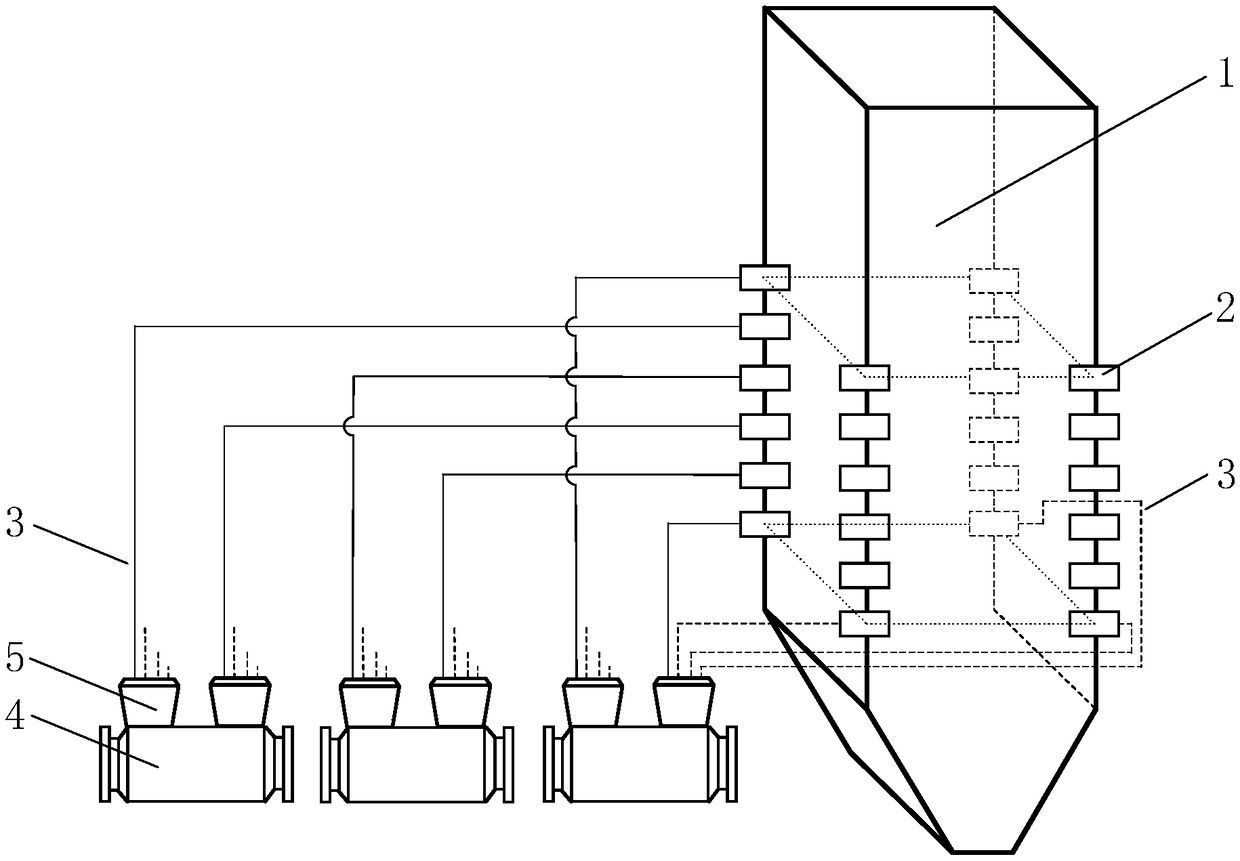
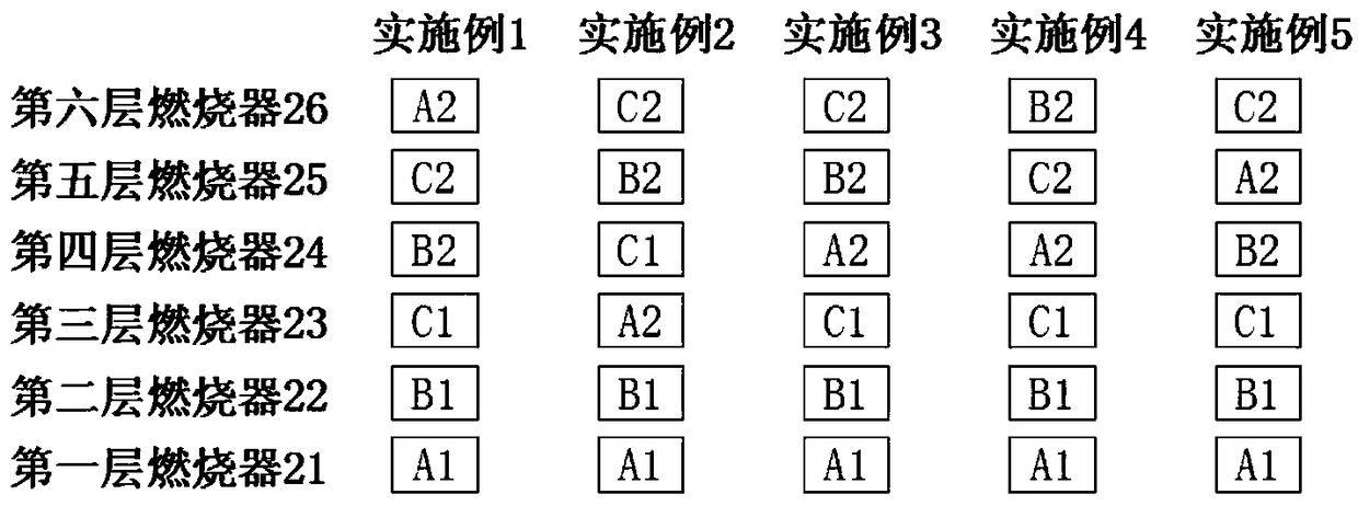
[0029] See attached figure 2 , 3 As shown, the first outlet A1 of the first double-inlet and double-outlet coal mill 41 is connected to the inlet of the first pulverized coal separator 51, and the outlet of the first pulverized coal separator 51 passes through the pulverized coal pipeline 3 They are respectively connected to the first layer of burners 21; the second outlet A2 of the first double-inlet and double-outlet coal mill 41 is connected to the inlet of the second pulverized coal separator 52, and the outlet of the second pulverized coal separator 52 The feed port is respectively connected to the sixth layer burner 26 through the pulverized coal pipeline 3;

[0030] The first outlet B1 of the second double-inlet and double-outlet coal mill 42 is connected to the inlet of the third pulverized coal separator 53, and the outlet of the third pulverized coal separator 53 is respectively connected to the first outlet of the pulverized coal separator 53 through the pulverize...

Embodiment 2

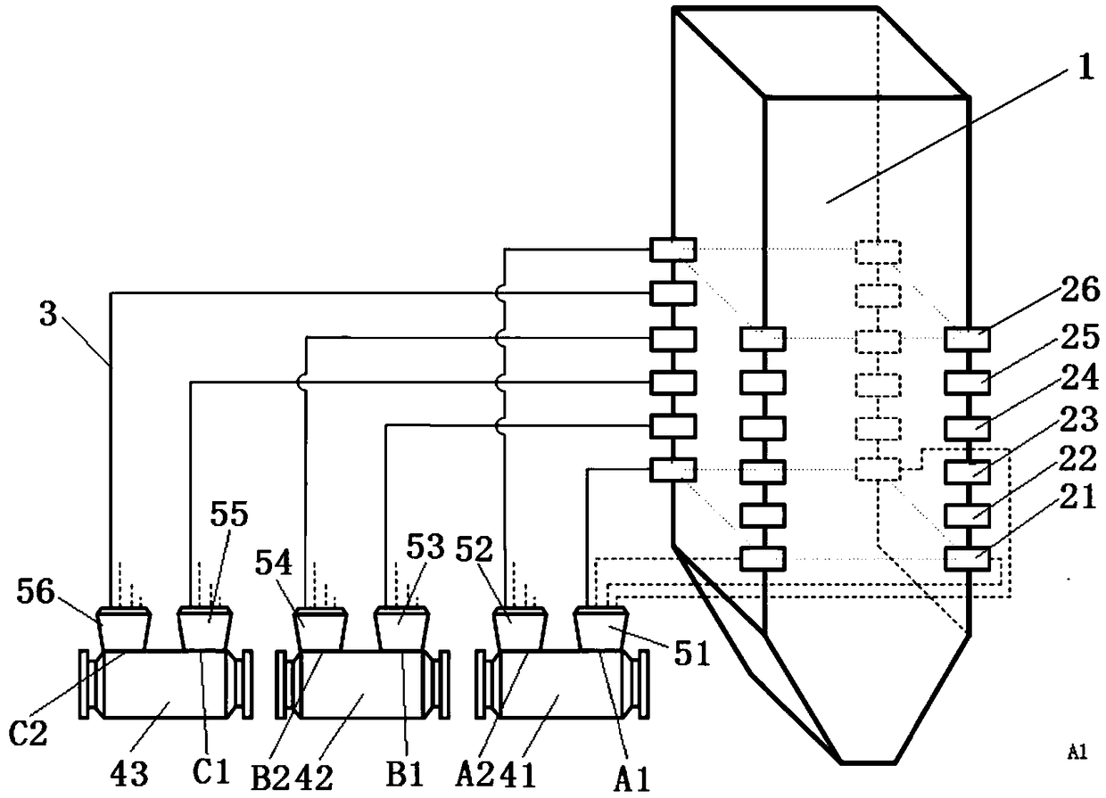
[0034] See attached figure 1 , 3 As shown, the first outlet A1 of the first double-inlet and double-outlet coal mill 41 is connected to the inlet of the first pulverized coal separator 51, and the outlet of the first pulverized coal separator 51 passes through the pulverized coal pipeline 3 They are respectively connected to the first layer of burners 21; the second outlet A2 of the first double-inlet and double-outlet coal mill 41 is connected to the inlet of the second pulverized coal separator 52, and the outlet of the second pulverized coal separator 52 The feed port is respectively connected to the third layer burner 23 through the pulverized coal pipeline 3;

[0035]The first outlet B1 of the second double-inlet and double-outlet coal mill 42 is connected to the inlet of the third pulverized coal separator 53, and the outlet of the third pulverized coal separator 53 is respectively connected to the first outlet of the pulverized coal separator 53 through the pulverized ...

Embodiment 3

[0038] See attached figure 1 , 3 As shown, the first outlet A1 of the first double-inlet and double-outlet coal mill 41 is connected to the inlet of the first pulverized coal separator 51, and the outlet of the first pulverized coal separator 51 passes through the pulverized coal pipeline 3 They are respectively connected to the first layer of burners 21; the second outlet A2 of the first double-inlet and double-outlet coal mill 41 is connected to the inlet of the second pulverized coal separator 52, and the outlet of the second pulverized coal separator 52 The feed port is respectively connected to the fourth layer burner 24 through the pulverized coal pipeline 3;

[0039] The first outlet B1 of the second double-inlet and double-outlet coal mill 42 is connected to the inlet of the third pulverized coal separator 53, and the outlet of the third pulverized coal separator 53 is respectively connected to the first outlet of the pulverized coal separator 53 through the pulverize...


PUM


Abstract

The invention discloses a flame center controllable coal pulverizing system mill dislocation pulverized coal pipeline arrangement structure which comprises a plurality of double-inlet and double-outlet coal mills, pulverized coal pipelines and a tangential boiler. Pulverized coal burners are arranged at corner areas of the tangential boiler along the height direction in a layered manner, each double-inlet and double-outlet coal mill is provided with a first discharging port and a second discharging port, the first discharging ports are connected with the pulverized coal burners at the corner areas of the tangential boiler at the same height through the pulverized coal pipelines, the second discharging ports are connected with the pulverized coal burners at the corner areas of the tangential boiler at the same height through the pulverized coal pipelines, and the first discharging port and the second discharging port of at least one double-inlet and double-outlet coal mill are connectedwith two layers of non-adjacent pulverized coal burners in the height direction of the corner areas of the tangential boiler through the pulverized coal pipelines. According to the structure, a flamecenter in the boiler cannot deflect some corner of a hearth when any coal mill is started and stopped, the elevation of the flame center of the tangential boiler is basically changed, flexible dispatching requirements of a rapid lifting load are met, and the fullness degree of a flame in the hearth is improved.

Description

technical field [0001] The invention belongs to the technical field of boilers, and in particular relates to an arrangement structure of dislocation pulverized coal pipelines of a pulverizing system with controllable flame center. Background technique [0002] Clean energy such as solar energy and wind energy are friendly to the environment, but subject to changes in natural conditions and large load fluctuations; the grid's requirements for new energy consumption capacity are gradually increasing, but coal-fired power generation units with rapid and deep peak-shaving capabilities are the key to supporting new energy As an important part of power generation, with the gradual increase in the installed capacity of new energy in the power grid, the demand for peak-shaving capacity of coal-fired generating units is also gradually increasing. [0003] The layout of the existing pulverized coal boiler pulverization system is generally as follows: [0004] 1. The pulverized coal s...

Claims


Application Information

Patent Timeline
IPC IPC(8): F23K3/00F23K1/00
CPCF23K1/00F23K3/00F23K2201/1006F23K2201/30F23K2203/10
Inventor 孙国俊范海鸿
Owner 苏州吉杰电力科技有限公司
Why Eureka
Try Eureka