Test circuit for infrared receiving head
A technology of infrared receiving head and test circuit, which is applied in the direction of electrical connection test, measurement of electricity, and measurement of electrical variables, etc., which can solve the problems of large error in manual reading, low test efficiency, and long time consumption, and improve the degree of automation , increase the test time, easy to use effect
- Summary
- Abstract
- Description
- Claims
- Application Information
AI Technical Summary
Problems solved by technology
Method used
Image

Examples
Embodiment 1
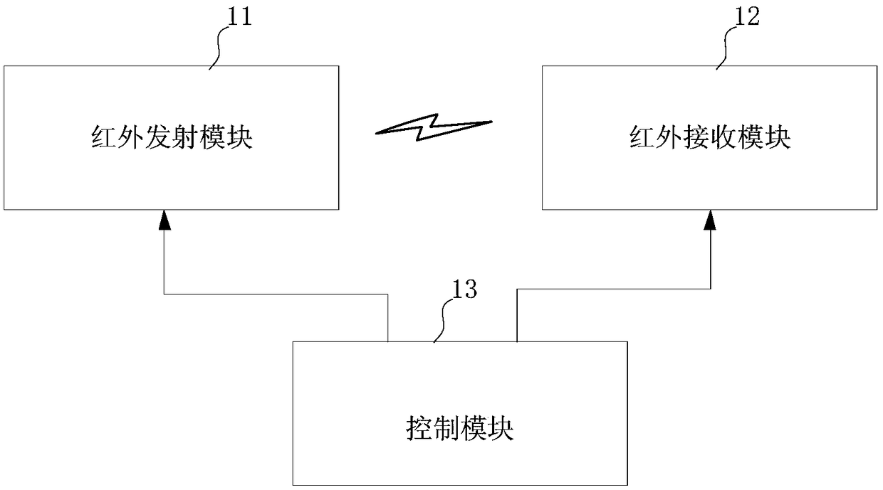
[0039] figure 1 This is a block diagram of a test circuit of an infrared receiving head provided in Embodiment 1 of the present invention. The test circuit of the infrared receiving head in this embodiment is used to perform compatibility testing on the infrared receiving head during material replacement. The test circuit of the infrared receiving head in this embodiment includes an infrared transmitting module 11 , an infrared receiving module 12 and a control module 13 .
[0040] The infrared emission module 11 is used for time-sharing to transmit a plurality of infrared emission signals of different intensities. In this embodiment, the infrared emitting module 11 at least includes one or more infrared emitters that emit or emit external light. The working current of the infrared transmitter can be adjusted through a preset time interval, such as 10 seconds or 20 seconds, so that the infrared transmitter can send infrared emission signals of different intensities outward to...
Embodiment 2
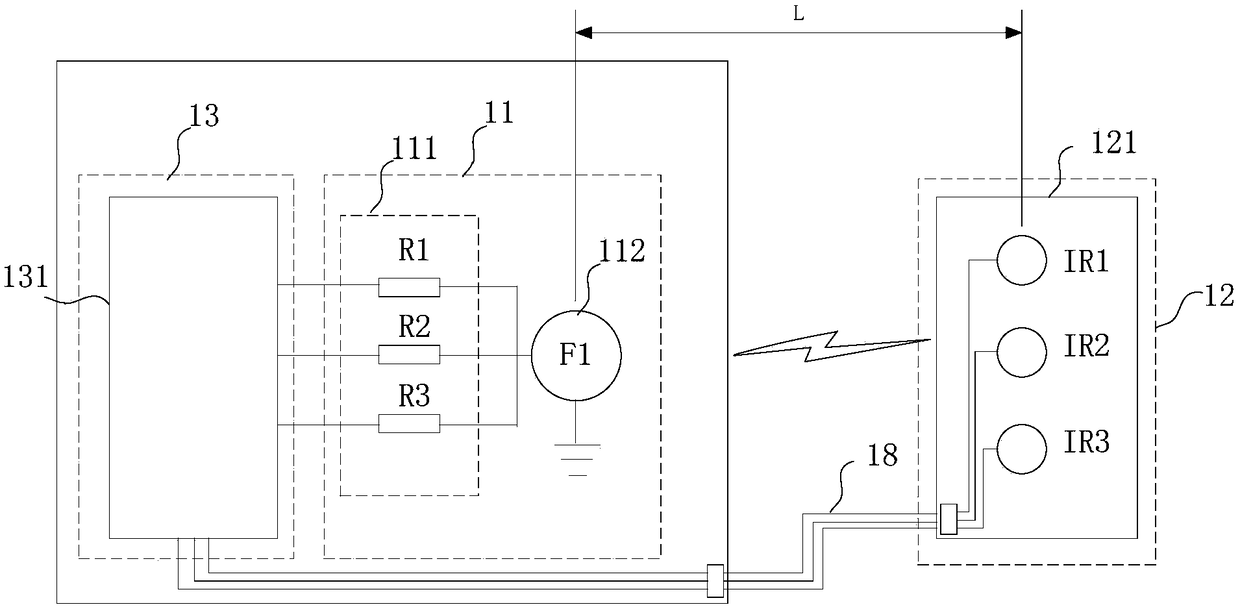
[0046] figure 2 This is a block diagram of a test circuit of an infrared receiving head provided by the second embodiment of the present invention. The test circuit of the infrared receiving head in this embodiment provides different resistances to control the intensity of the infrared emission signal, so as to realize the detection of the infrared receiving head in the material. Compatibility testing during replacement. The test circuit of the infrared receiving head in this embodiment includes an infrared transmitting module 11 , an infrared receiving module 12 and a control module 13 .
[0047] The infrared emission module 11 includes a resistance module 111 and an infrared transmitter 112 . The resistance module 111 is used for providing various resistances with different resistance values, and one end of the resistance module 111 is connected to the infrared transmitter 112 . In this embodiment, the resistor module 111 is a plurality of resistors with different resistan...
Embodiment 3
[0054] Figure 5 This is a block diagram of a test circuit of an infrared receiving head provided by the third embodiment of the present invention. The test circuit of the infrared receiving head in this embodiment provides a display device for displaying the compatibility test of the infrared receiving head during the material replacement process. result. The test circuit of the infrared receiving head in this embodiment includes an infrared transmitting module 11 , an infrared receiving module 12 , a control module 13 and a display device 14 .
[0055] The infrared receiving module 12 includes a detection circuit board 121, and the detection circuit board 121 is used for detachably connecting at least one infrared receiving head to be tested. In this embodiment, the infrared receiving heads to be tested are three IR1-IR3.
[0056] The infrared emission module 11 includes a resistance module 111 , an infrared transmitter 112 and a switch module 113 .
[0057] The resistor m...
PUM
 Abstract
Description
Claims
Application Information
 - R&D
- Intellectual Property
- Life Sciences
- Materials
- Tech Scout
- Unparalleled Data Quality
- Higher Quality Content
- 60% Fewer Hallucinations
Browse by: Latest US Patents, China's latest patents, Technical Efficacy Thesaurus, Application Domain, Technology Topic, Popular Technical Reports.
© 2025 PatSnap. All rights reserved.Legal|Privacy policy|Modern Slavery Act Transparency Statement|Sitemap|About US| Contact US: help@patsnap.com