Obstacle detection method and device, electronic device, vehicle and storage medium

An obstacle detection and obstacle technology, applied in obstacle detection, vehicles and storage media fields, can solve problems such as inability to achieve accurate and effective detection, missed detection by lidar, etc.

Active Publication Date: 2019-01-25
APOLLO INTELLIGENT DRIVING (BEIJING) TECHNOLOGY CO LTD
View PDF11 Cites 33 Cited by
  • Summary
  • Abstract
  • Description
  • Claims
  • Application Information

AI Technical Summary

Problems solved by technology

For example, certain materials that are particularly black may absorb too much laser light, causing lidar to miss detection
[0006]

Method used


Image

  • Obstacle detection method and device, electronic device, vehicle and storage medium
  • Obstacle detection method and device, electronic device, vehicle and storage medium
  • Obstacle detection method and device, electronic device, vehicle and storage medium

Examples


Embodiment 1

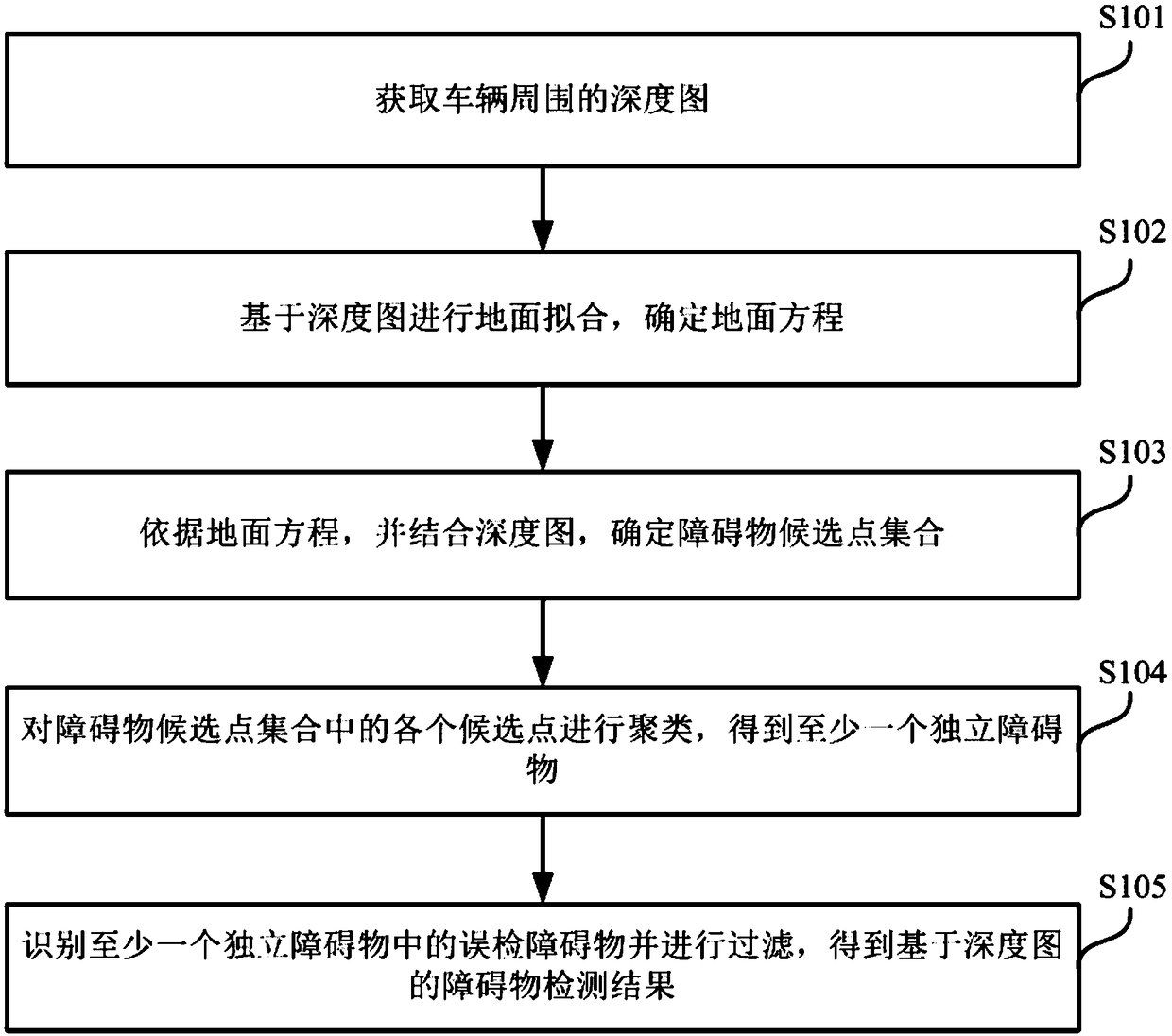
[0060] figure 1 This is a schematic flowchart of the obstacle detection method provided in Embodiment 1 of the present invention. The method may be executed by an obstacle detection device or an electronic device, and the device or electronic device may be implemented by software and / or hardware. The device or electronic device The device can be integrated in any smart device with network communication capabilities, such as a vehicle, which can be an unmanned vehicle. like figure 1 As shown, the obstacle detection method may include the following steps:

[0061] S101. Obtain a depth map around the vehicle.

[0062] In computer vision systems, 3D scene information provides more possibilities for various computer vision applications such as image segmentation, target detection, and object tracking. a wide range of applications. In 3D computer graphics, a depth map is an image or image channel that contains information about the distance to the surface of a scene object from ...

Embodiment 2

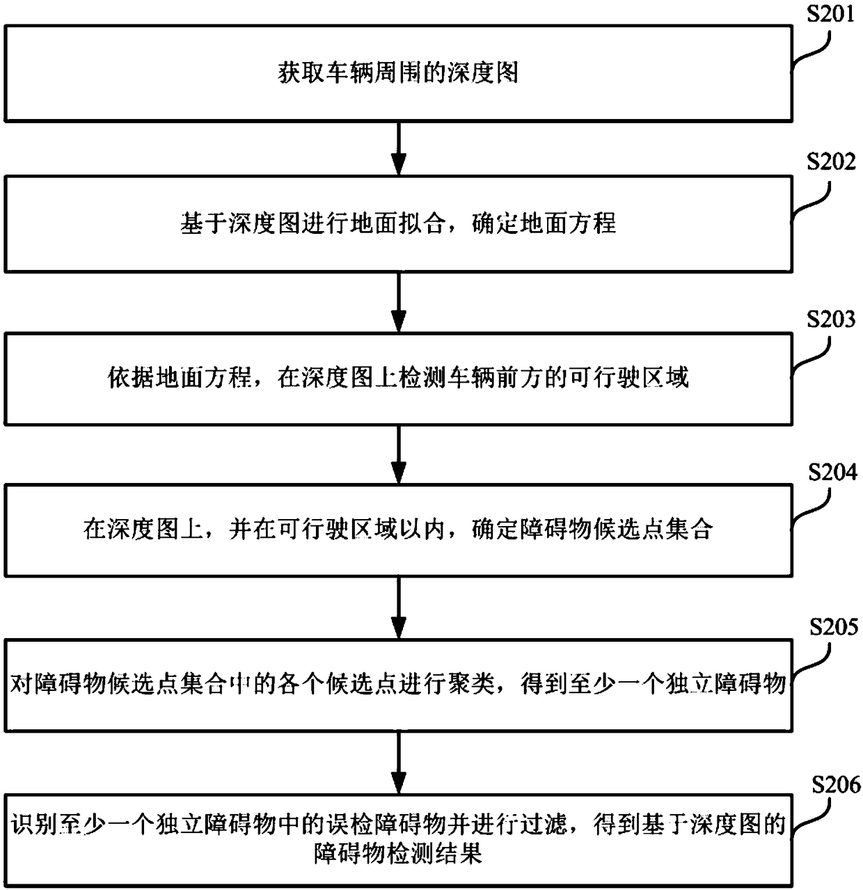
[0075] figure 2 This is a schematic flowchart of the obstacle detection method provided in the second embodiment of the present invention. like figure 2 As shown, the obstacle detection method may include the following steps:

[0076] S201. Obtain a depth map around the vehicle.

[0077] S202. Perform ground fitting based on the depth map, and determine a ground equation.

[0078] S203. According to the ground equation, detect the drivable area in front of the vehicle on the depth map.

[0079] In a specific embodiment of the present invention, the electronic device can detect the drivable area in front of the vehicle on the depth map according to the ground equation. That is, after the electronic device acquires the depth map around the vehicle, the electronic device can detect the drivable area and the non-drivable area in front of the vehicle on the depth map. Specifically, the electronic device can calculate the touchdown point on the depth map according to the grou...

Embodiment 3

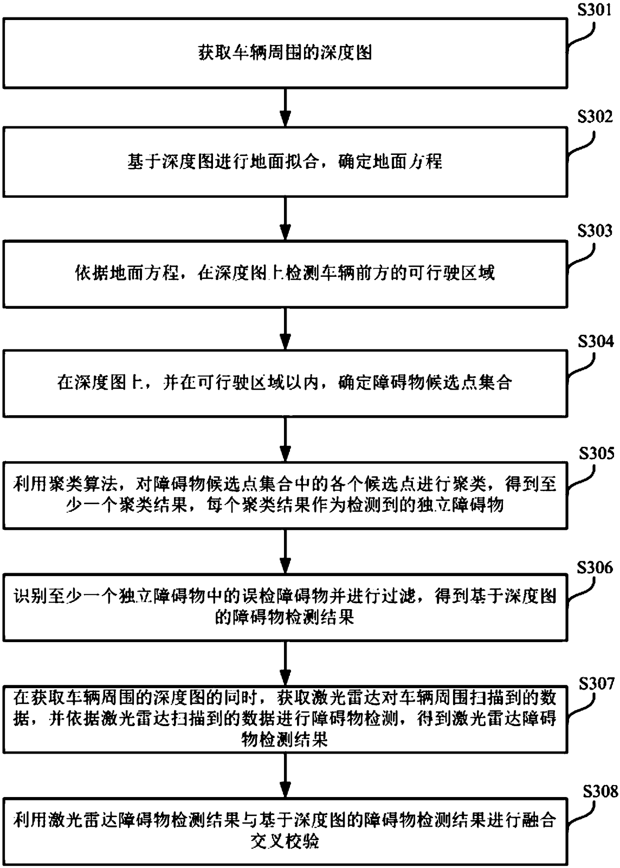
[0088] image 3 This is a schematic flowchart of the obstacle detection method provided in Embodiment 3 of the present invention. like image 3 As shown, the obstacle detection method may include the following steps:

[0089] S301. Obtain a depth map around the vehicle.

[0090] S302. Perform ground fitting based on the depth map, and determine a ground equation.

[0091] S303. According to the ground equation, detect the drivable area in front of the vehicle on the depth map.

[0092] S304 , on the depth map and within the drivable area, determine a set of candidate obstacle points.

[0093] S305. Use a clustering algorithm to cluster each candidate point in the obstacle candidate point set to obtain at least one clustering result, and each clustering result is used as a detected independent obstacle.

[0094] S306. Identify and filter the falsely detected obstacles in at least one independent obstacle to obtain an obstacle detection result based on the depth map.

[00...


PUM


Abstract

The embodiment of the invention discloses an obstacle detection method and device, a vehicle and a storage medium. The method comprises the following steps: obtaining a depth map around a vehicle; performing ground fitting based on the depth map to determine a ground equation; determining an obstacle candidate point set according to the ground equation and based on the depth map; clustering each candidate point in the obstacle candidate point set to obtain at least one independent obstacle; and identifying and filterng false detection obstacles in at least one independent obstacle to obtain anobstacle detection result based on the depth map. It can avoid the obstacle missing detection problem caused by the sparse sampling points when using the laser radar for detection; and the missing detection problem caused due to the fact that since not all types of obstacles can be used as samples for model training when a monocular camera is adopted for detection, the types of untrained samplescannot be detected, can also be avoided.

Description

technical field [0001] Embodiments of the present invention relate to unmanned vehicle technology, and in particular, to an obstacle detection method, device, electronic device, vehicle, and storage medium. Background technique [0002] Unmanned vehicles refer to the perception of the surrounding environment of the vehicle through various sensors, and control the steering and speed of the vehicle according to the road, vehicle position and obstacles obtained by the perception, so that the vehicle can be safely and reliably on the road. drive. Among them, the obstacles may include stone piers, balls, fire hydrants, etc. appearing on the road. [0003] Monocular cameras and lidars are both important sensors in autonomous driving systems. These sensors can be used to perceive the surrounding environment of the vehicle, such as obstacle detection, classification, and tracking. Each of these sensors has its own strengths and limitations. [0004] Using a monocular camera for o...

Claims


Application Information

Patent Timeline
IPC IPC(8): G06K9/00G06K9/62G01S17/93G01S17/89G01S17/931
CPCG01S17/89G01S17/931G06V20/58G06F18/23G06F18/214G06V20/64G06T7/62G06T7/50H04N13/271G01S7/4802G01S17/42G06T2207/10028G06T2207/30261H04N2013/0081G06F18/217G06F18/253G06F18/2148
Inventor 陈东明孙迅王亮
Owner APOLLO INTELLIGENT DRIVING (BEIJING) TECHNOLOGY CO LTD
Why Eureka
Try Eureka